སྒྱུ་རྩལ
མཛེས་སྡུག་དང་བདེ་ཐང
བཟོ་རིག
རིག་གནས་དང་ལོ་རྒྱུས
དགའ་སྟོན
ཁོར་ཡུག
ཟས་དང་བཏུང་རྫས
ཕྱིར་འཕྲུལ་རིག
ཚན་རིག
རྩེད་འགྲན
རིག་རྩལ
གྱོན་རུང
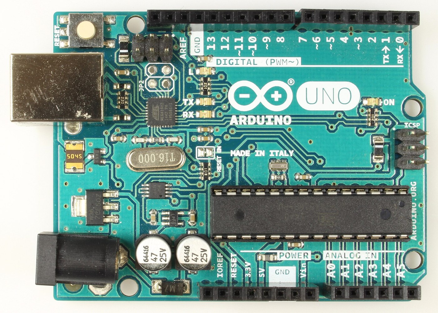


Arduino Uno R3: Assembled from Arduino's Open UNO-TH Rev3e Design Files and Flashed over ICSP
The Arduino Uno R3 is open hardware: Arduino publishes its schematic and board layout. This blueprint builds one from those files, part by part, then loads the firmware into its two processors.
Result: an Arduino Uno R3. An ATmega328P (16 MHz, 32 kB flash, 2 kB SRAM, 1 kB EEPROM) runs your programs; an ATmega16U2 turns USB into its serial link. It runs from USB (5.5 V at most) or 6-20 V at the DC jack.
Source: Arduino UNO-TH_Rev3e design files and the A000066 schematic and datasheet (Arduino, CC BY-SA). Unknown: how every bought part is made; no public source in hand says. The soldering method is ours. Picture: Wikimedia Commons.
མཐོ་རིམ
1 day
ལམ་སྟོན
1
1
Get the bare board
Get the bare board
Have the two-layer board made to Arduino's UNO-TH_Rev3e board layout (the .brd file of the design files). Check it against the schematic before fitting anything.
གོམ་པ་འདིའི་རྫས་རིགས:
 PCB ལེབ1 UNO-TH Rev3e layout
ལག་ཆས་དགོས་མཁོ:
 ཆེ་བཟོའི་ལུབ།
2
2
Fit the small surface-mount parts
Fit the small surface-mount parts
Solder the chip parts to their marked places: resistor arrays RN1 (10K), RN2 and RN4 (1K), RN3 (22R); R1, R2 (1M); capacitors C1, C2, C4-C7, C10 (100n), C3, C8 (1u), C9, C11 (22p); varistors Z1, Z2; ferrite bead L1; inductor L2 (10 uH); diodes D2, D3; LEDs ON (green), L, RX, TX (yellow). Ours: flux, tweezers and hot air or a fine iron, checked under a loupe.
གོམ་པ་འདིའི་རྫས་རིགས:
 ཅིཔ་ རེ་ཟིསི་ཊར་ ཕྲེང་བ།4 RN1-RN4
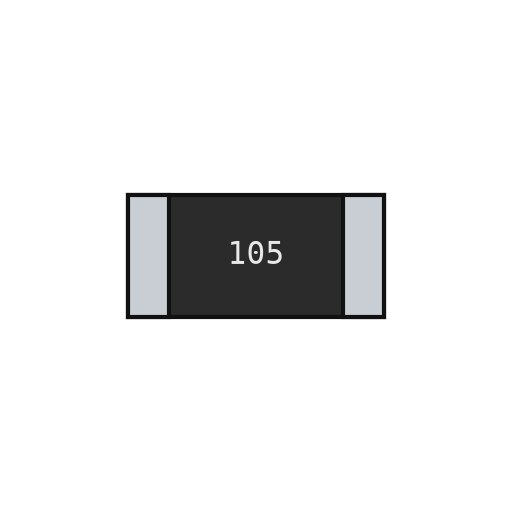 ཅིཔ་ རེ་ཟིསི་ཊར།2 1M
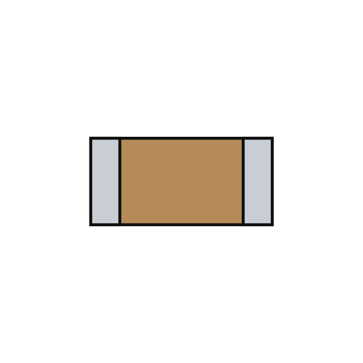 སི་ར་མིཀ་ ཅིཔ་ ཀེ་པེ་སི་ཊར།11 7x100n, 2x1u, 2x22p
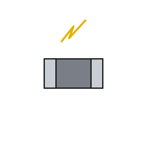 ཅིཔ་ ཝེ་རིསི་ཊར།2 Z1, Z2
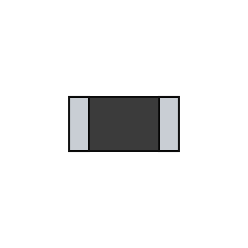 ཕེ་རའིཊ་ གཟི།1 L1
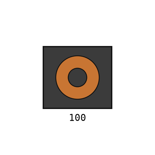 ཁ་ཐོག་སྒྲིག་ ཨིན་ཌཀ་ཊར།1 L2
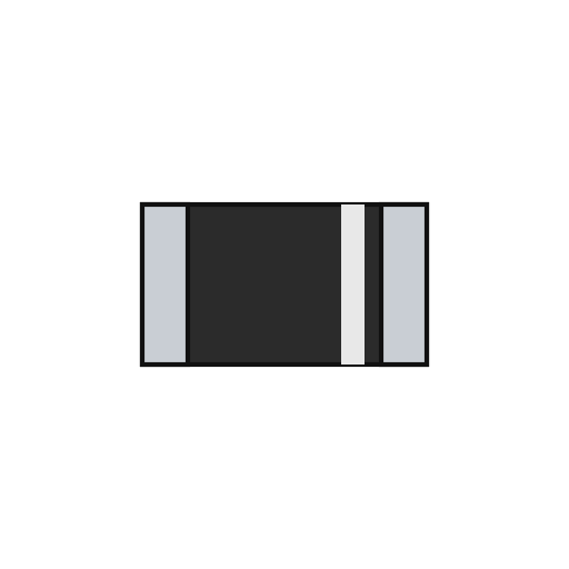 ཁ་ཐོག་སྒྲིག་ ཌའི་ཨོཌ།2 D2, D3
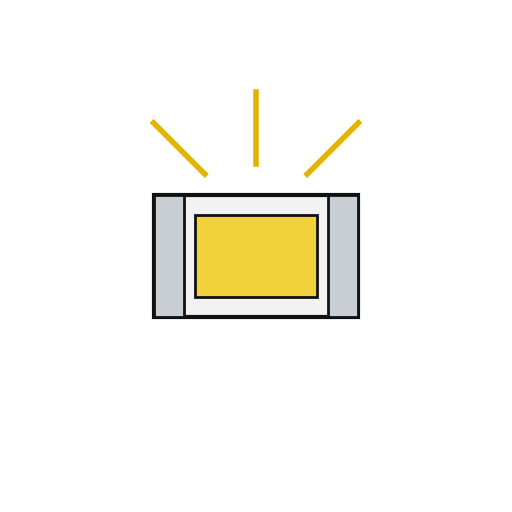 ཅིཔ་ LED4 1 green, 3 yellow
 ཞ་སྦྱར་རྫས་ཀྱི་སྐུད་པ1 a little
ལག་ཆས་དགོས་མཁོ:
 ཞུ་རོགས་རྫས
 རྩེ་རྣོ་བའི་ཀམ།
 རླུང་ཚན་གྱི་བཟོ་བཅོས་ཁང་།
 ཞ་བཏབ་ནིའི་ལྕགས།ཆེ་བཟོའི་ལུབ།
3
3
Fit the power and chip parts
Fit the power and chip parts
Solder the ATmega16U2 (U3), the 16 MHz resonator Y2 and crystal Y1, the 5 V regulator NCP1117 (U1) and 3.3 V regulator LP2985 (U2), the LMV358 op-amp (U5), the FDN340P transistor (T1), the M7 diode (D1), the 500 mA resettable fuse (F1) and the 47 uF capacitors PC1, PC2 with their polarity as marked.
གོམ་པ་འདིའི་རྫས་རིགས:
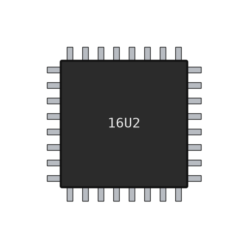 ATmega16U2 མའི་ཀོརོ་ཀཱན་ཊོ་ལར།1 U3
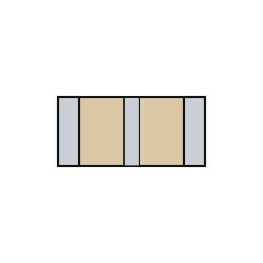 པི་ཛོ་ སི་ར་མིཀ་ རི་ཛོ་ནེ་ཊར།1 Y2
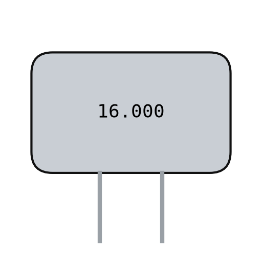 ཀྭརཙ་ ཤེལ་རྡོ།1 Y1
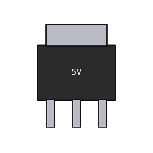 ཐིག་ཕྲེང་ གློག་ཤུགས་ ཚད་འཛིན་ཆས།2 U1 5 V, U2 3.3 V
 ཨོཔ་ཨེམ་པི་ IC1 U5 LMV358
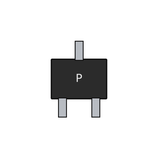 P-རྒྱུ་ལམ་ MOSFET1 T1ཁ་ཐོག་སྒྲིག་ ཌའི་ཨོཌ།1 D1 M7
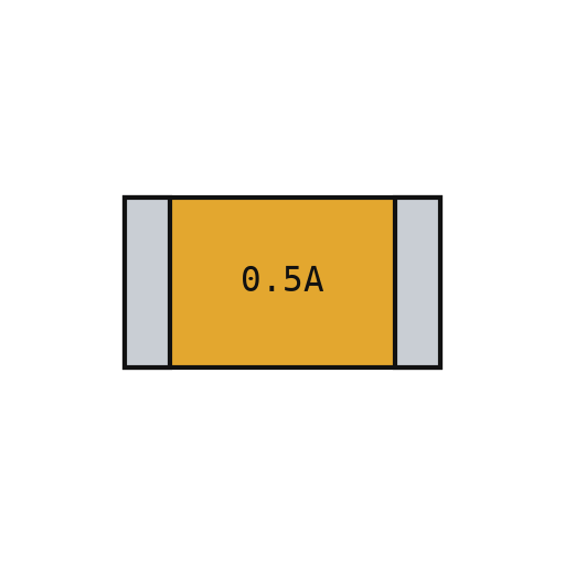 ལོག་སྒྲིག་ཚུགས་པའི་ ཕིའུཟ།1 F1
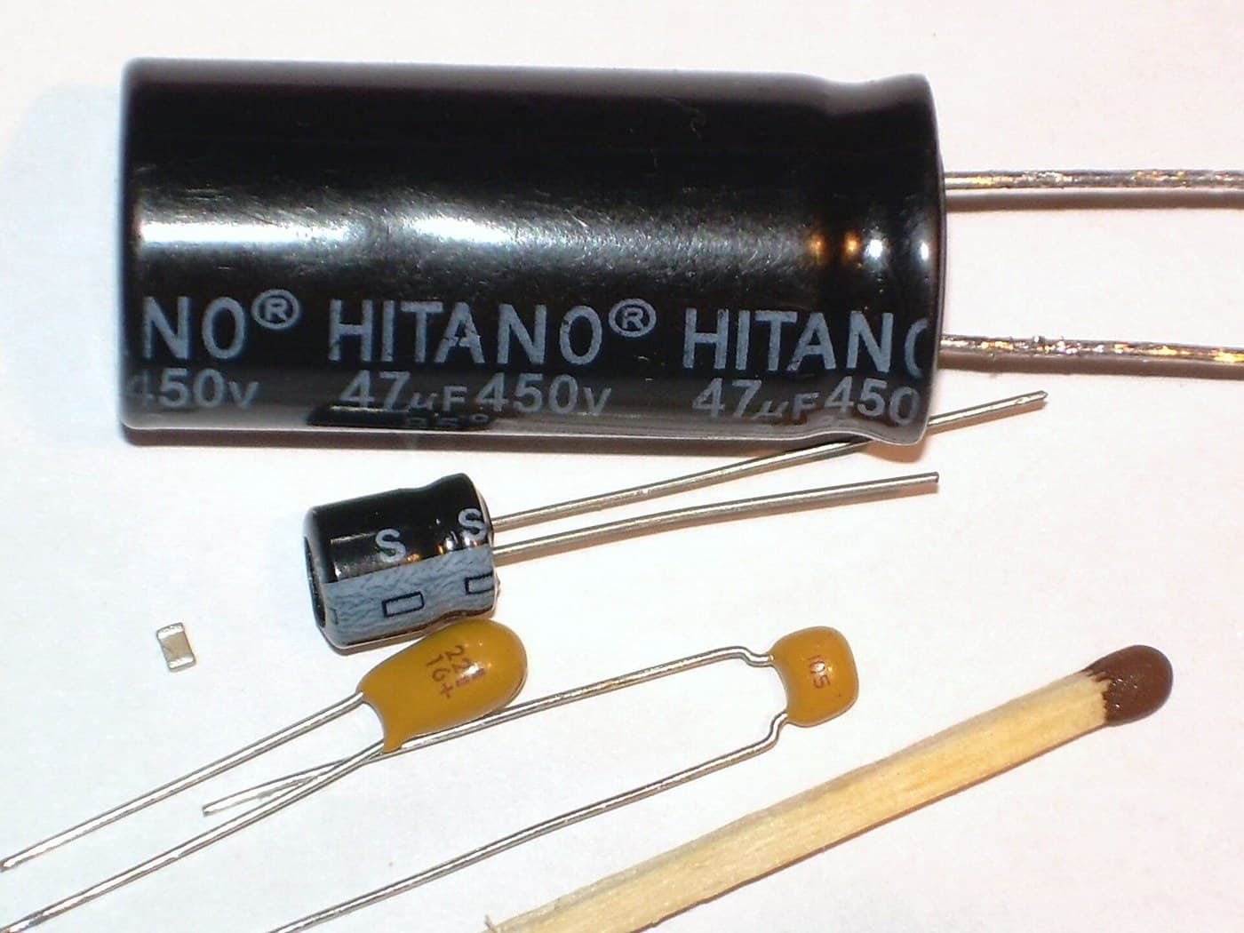
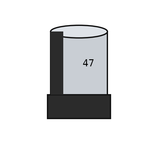 ཕྱོགས་མཐའ་ཅན་ ཅིཔ་ ཀེ་པེ་སི་ཊར།2 PC1, PC2ཞ་སྦྱར་རྫས་ཀྱི་སྐུད་པ1 a little
ལག་ཆས་དགོས་མཁོ:
ཞུ་རོགས་རྫསརྩེ་རྣོ་བའི་ཀམ།རླུང་ཚན་གྱི་བཟོ་བཅོས་ཁང་།ཞ་བཏབ་ནིའི་ལྕགས།ཆེ་བཟོའི་ལུབ།4
4
Fit the through-hole parts
Fit the through-hole parts
Solder the USB-B socket (X2), the DC jack (X1), the reset switch, the female headers (one 10-way, two 8-way, one 6-way) and the two 2x3 ICSP headers. Seat the ATmega328P in its place (ZU4).
གོམ་པ་འདིའི་རྫས་རིགས:
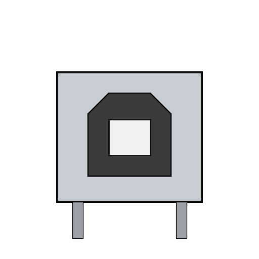 USB-B ཀ་ཏོག།1 X2
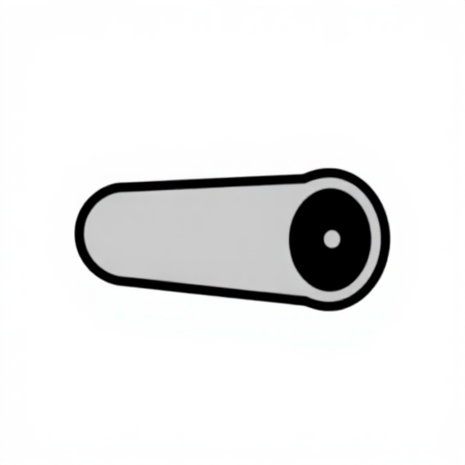 གློག་ཤུགས་ཀྱི་ཁུང་སྒོར།1 X1
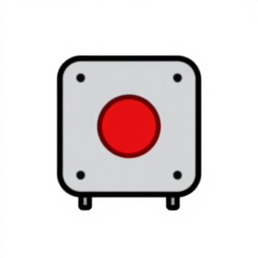 གནོན་ཐེབས།1 RESET
 ཟུར་ཐིག་མཐུད་ཁྲམ།6 10x1, 2x 8x1, 6x1 female; 2x 3x2 ICSP
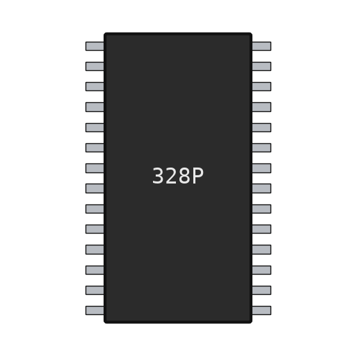 ATmega328P མའི་ཀོརོ་ཀཱན་ཊོ་ལར།1 ZU4ཞ་སྦྱར་རྫས་ཀྱི་སྐུད་པ1 as needed
ལག་ཆས་དགོས་མཁོ:
ཞ་བཏབ་ནིའི་ལྕགས།5
5
Flash and check
Flash and check
Check with a meter that 5 V and GND are not shorted. Through the ICSP headers, load the USB-to-serial firmware into the ATmega16U2 and the bootloader into the ATmega328P. Plug in USB: the green ON LED lights, and the blink test in the next step flashes the L LED. Ours: an AVR ISP programmer and a multimeter.
གོམ་པ་འདིའི་རྫས་རིགས:
 Arduino Uno བརྟན་མཉེན།1 download
ལག་ཆས་དགོས་མཁོ:
 མཱལ་ཊི་མི་ཊར།
 AVR ISP ལས་རིམ་འབྲི་ཆས།
 USB-B ཞགས་པ།
6
6
The blink test
The blink test
blink_test.ino: the same check as Arduino's Blink example. Upload it over USB from the Arduino IDE with the board set to Arduino Uno; the L LED on pin 13 turns on for one second and off for one second, over and over. If it does, both processors, the USB link and the bootloader work.
blink_test.inocpp
ལག་ཆས་དགོས་མཁོ:
USB-B ཞགས་པ།རྫས་རིགས
24- 1 UNO-TH Rev3e layoutས་ཆ་འཛིན
- 4 RN1-RN4ས་ཆ་འཛིན
- 2 1Mས་ཆ་འཛིན
- 11 7x100n, 2x1u, 2x22pས་ཆ་འཛིན
- 2 Z1, Z2ས་ཆ་འཛིན
- 1 L1ས་ཆ་འཛིན
- ས་ཆ་འཛིན
- 1 D1 M7ས་ཆ་འཛིན
- 4 1 green, 3 yellowས་ཆ་འཛིན
- 1 as neededས་ཆ་འཛིན
- ས་ཆ་འཛིན
- ས་ཆ་འཛིན
- 1 Y1ས་ཆ་འཛིན
- 2 U1 5 V, U2 3.3 Vས་ཆ་འཛིན
- 1 U5 LMV358ས་ཆ་འཛིན
- ས་ཆ་འཛིན
- ས་ཆ་འཛིན
- 2 PC1, PC2ས་ཆ་འཛིན
- 1 X2ས་ཆ་འཛིན
- ས་ཆ་འཛིན
- ས་ཆ་འཛིན
- ས་ཆ་འཛིན
- ས་ཆ་འཛིན
- 1 downloadས་ཆ་འཛིན
ལག་ཆས་དགོས་མཁོ
8- ས་ཆ་འཛིན
- ས་ཆ་འཛིན
- ས་ཆ་འཛིན
- ས་ཆ་འཛིན
- 2 vendors sell this, none ship to you yetས་ཆ་འཛིན
- ས་ཆ་འཛིན
- ས་ཆ་འཛིན
- 1 vendor sell this, none ship to you yetས་ཆ་འཛིན
བིལུ་པིརིན་ཊི་འདི་གིས་བཟོ་མི
འབྲེལ་ཡོད་བིལུ་པིརིན་ཊི
བིལུ་པིརིན་ཊི་འདི་ཚུ་ཐབས་ལམ་དང་རྫས་རིགས། སྤྱི་ཆོས་བགོ་བཤའ་བྱེད
CC0 སྤྱི་དབང
བིལུ་པིརིན་ཊི་འདི་CC0 འོག་བཀྲམས་ཡོད། ཁྱེད་རང་གིས་ཆོག་མཆན་མ་བཞེས་པར་ཕབ་ལེན་དང་བཟོ་བཅོས། བགོ་བཤའ། དགོས་མཁོ་གང་ལའང་བཀོལ་སྤྱོད་བྱས་ཆོག
བཟོ་མཁན་ལ་རྒྱབ་སྐྱོར་བྱེད་པའི་ཆེད་ཁོང་ཚོའི་བིལུ་པིརིན་ཊི་བརྒྱུད་ཐོན་སྐྱེད་ཉོ། བཟོ་མཁན་གྱིས བཟོ་མཁན་གྱི་ཁེ་ཕོགས ཚོང་པས་གཏན་འཁེལ་བྱས་པ། ཡང་ན་བིལུ་པིརིན་ཊི་འདིའི་པར་གསར་བཟོས་ཏེ་ཁྱེད་རང་གི་བིལུ་པིརིན་ཊི་ནང་མཐུད་སྦྲེལ་བྱས་ཏེ་ཡོང་སྒོ་བགོ་བཤའ་བྱེད།