སྒྱུ་རྩལ
མཛེས་སྡུག་དང་བདེ་ཐང
བཟོ་རིག
རིག་གནས་དང་ལོ་རྒྱུས
དགའ་སྟོན
ཁོར་ཡུག
ཟས་དང་བཏུང་རྫས
ཕྱིར་འཕྲུལ་རིག
ཚན་རིག
རྩེད་འགྲན
རིག་རྩལ
གྱོན་རུང
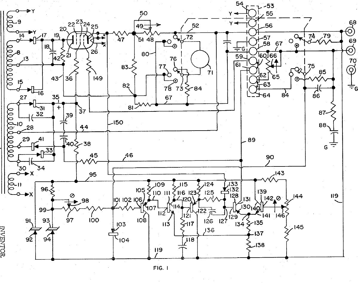


Bench Power Supply: Regulated, with Adjustable Current Limit and a Pentode Pass Tube (Gately, Forbro, US 3,243,690, 1966)
An adjustable bench supply that holds its output voltage steady and lets you set the most current it will deliver, so a circuit under test cannot be damaged. A pentode tube in series with the output is the regulator; a bridge with Zener references and a five-transistor amplifier keeps the output equal to the setting of one knob. A meter switch reads volts, amps, and the current limit, which can be set without disturbing the voltage.
Result: a regulated DC bench supply with adjustable current limiting.
Source: J. R. Gately (Forbro Design), US 3,243,690 (1966). Unknown: all component values and the output rating. Picture: the patent drawing.
མཐོ་རིམ
Unknown
ལམ་སྟོན
1
1
Wire the mains side
Wire the mains side
In a case, wire the power cord through a switch and a fuse to the primary of a transformer with four secondaries, and put a neon lamp across the primary to show the supply is on. One secondary (6.3 V) goes to two terminals for outside use, one heats the pentode, one is the main supply and one the bias supply. Ours: the case. Not given: the other winding voltages.
གོམ་པ་འདིའི་རྫས་རིགས:
 ཨ་ལུ་མི་ནིཡམ་གྱི་སྒྲོམ།1 case
 ཕལག་ཡོད་པའི་ གློག་སྐུད་ལྷབ་ལྷབ།1 དུམ་བུ།
 འཕར་སྒུལ་སྒོ་ལྕགས།1 དུམ་བུ།
 ཞུ་ཐིག།1 དུམ་བུ།
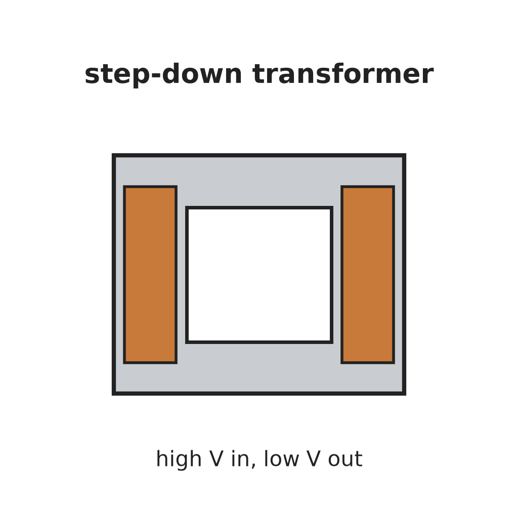 གློག་ཤུགས་འབབ་བཏང་གི་ཊྲཱནས་ཕོར་མར1 four secondaries
 ནེ་ཨོན་བརྡ་སྟོན་གློག་མེ།1 དུམ་བུ།
 མཐུད་ཀ་བ།2 6.3 V terminals
ལག་ཆས་དགོས་མཁོ:
 ལག་འཕྲུལ་ཁུང་བཏོན
 སྒྲོག་བསྐོར་ཆས་ཆ་ཚང་།
2
2
Build the rectifiers
Build the rectifiers
Rectify the centre-tapped main winding with two rectifiers and smooth it with a capacitor. From the bias winding make two more supplies: one through two rectifiers with by-pass capacitors to a smoothing capacitor, for the pentode's screen and the reference circuit; the other through one rectifier and a capacitor, for the pentode's grid bias. Not given: the values.
གོམ་པ་འདིའི་རྫས་རིགས:
 ཌའི་ཨོཌ།5 rectifiers
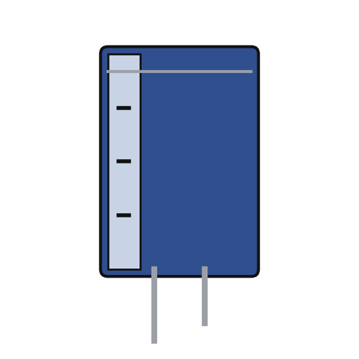 གློག་ཞུན་ ཀེ་པེ་སི་ཊར།3 smoothing
 ཀོན་ཌེན་སར་ཆ་ཚན།1 by-pass
 ཞ་སྦྱར་རྫས་ཀྱི་སྐུད་པ1 as needed
ལག་ཆས་དགོས་མཁོ:
 ཞ་བཏབ་ནིའི་ལྕགས།
3
3
Fit the pass tube and reference
Fit the pass tube and reference
Put the pentode in series with the positive output: plate to the main supply, cathode through two current-sensing resistors (one fixed, one adjustable) to the + output terminal; suppressor tied to the cathode, screen fed through a resistor. Build the reference: a Zener fed through a resistor feeds a second Zener at constant current, giving a fixed voltage. Against it set two resistors and the voltage-control variable resistor: the output voltage is proportional to that resistor's setting. Not given: the tube type and values.
གོམ་པ་འདིའི་རྫས་རིགས:
 པེན་ཊོཌ་གློག་སྦུག1 series pass tube
 ཛི་ནར་ཌའི་ཡོཌ།2 དུམ་བུ།
 འགོག་ཤུགས།1 ཚན་པ།
 རི་ཡོ་སི་ཊེཊ།2 voltage control, current-limit rangeམཐུད་ཀ་བ།2 output + and -ཞ་སྦྱར་རྫས་ཀྱི་སྐུད་པ1 as needed
ལག་ཆས་དགོས་མཁོ:
ཞ་བཏབ་ནིའི་ལྕགས།4
4
Build the error amplifier and current limit
Build the error amplifier and current limit
Build a five-transistor amplifier that drives the pentode's grid to keep the bridge balanced: a PNP emitter follower, an NPN stage, a PNP emitter follower with a resistor-capacitor roll-off against oscillation, a PNP driver whose base resistor has a capacitor across it for quick response, and an NPN clamp whose base is set by a potentiometer. Feed the voltage across the current-sensing resistors to the driver's base through a diode: above the limit it takes over and turns the pentode down. Choose the fixed sensing resistor to limit at about 125 % of rated current, trim with the potentiometer, and use the adjustable one to set lower limits. Not given: the transistor types and values.
གོམ་པ་འདིའི་རྫས་རིགས:
 པི་ཨེན་པི་ ཊཱན་སི་སི་ཊར།3 དུམ་བུ།
 NPN ཊུརེན་སིསི་ཊར།2 དུམ་བུ།ཌའི་ཨོཌ།1 དུམ་བུ།
 པོ་ཊེན་ཤོ་མི་ཊར།1 དུམ་བུ།ཀོན་ཌེན་སར་ཆ་ཚན།1 roll-off, speed-upའགོག་ཤུགས།1 ཚན་པ།ཞ་སྦྱར་རྫས་ཀྱི་སྐུད་པ1 as needed
ལག་ཆས་དགོས་མཁོ:
ཞ་བཏབ་ནིའི་ལྕགས།5
5
Fit the meter and use it
Fit the meter and use it
Fit a meter with a four-pole, three-position switch. Position 1 reads output volts through a multiplier resistor; position 2 reads current across a shunt in the negative line; position 3 (spring-return) puts a load resistor across the output and swaps a fixed resistor for the voltage control, so you can turn the limit control until the current limits at the value you want, without touching the voltage setting. Release the switch and use the supply.
གོམ་པ་འདིའི་རྫས་རིགས:
 འགུལ་བའི་གློག་འཁྱིལ་ཅན་གྱི་པེ་ནཱལ་འཇལ་ཆས།1 དུམ་བུ།
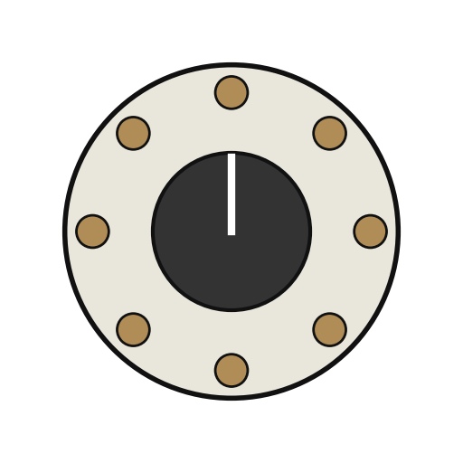 འཁོར་ལོ་ གློག་སྒོ།1 4-pole, 3-positionའགོག་ཤུགས།1 multiplier, shunt, load resistors
 ངོ་མ་ཤེས་པའི་རྒྱུ་ཆ།1 terminal strip
ལག་ཆས་དགོས་མཁོ:
ཞ་བཏབ་ནིའི་ལྕགས།སྒྲོག་བསྐོར་ཆས་ཆ་ཚང་།རྫས་རིགས
21- 1 caseས་ཆ་འཛིན
- 1 དུམ་བུ།ས་ཆ་འཛིན
- ས་ཆ་འཛིན
- 1 དུམ་བུ།ས་ཆ་འཛིན
- 1 four secondariesས་ཆ་འཛིན
- 1 དུམ་བུ།ས་ཆ་འཛིན
- ས་ཆ་འཛིན
- 1 དུམ་བུ།ས་ཆ་འཛིན
- 3 smoothingས་ཆ་འཛིན
- 1 roll-off, speed-upས་ཆ་འཛིན
- 3 as neededས་ཆ་འཛིན
- 1 series pass tubeས་ཆ་འཛིན
- 2 དུམ་བུ།ས་ཆ་འཛིན
- 1 multiplier, shunt, load resistorsས་ཆ་འཛིན
- 2 voltage control, current-limit rangeས་ཆ་འཛིན
- 3 དུམ་བུ།ས་ཆ་འཛིན
- 2 དུམ་བུ།ས་ཆ་འཛིན
- ས་ཆ་འཛིན
- ས་ཆ་འཛིན
- 1 4-pole, 3-positionས་ཆ་འཛིན
- 1 terminal stripས་ཆ་འཛིན
བིལུ་པིརིན་ཊི་འདི་གིས་བཟོ་མི

CC0 སྤྱི་དབང
བིལུ་པིརིན་ཊི་འདི་CC0 འོག་བཀྲམས་ཡོད། ཁྱེད་རང་གིས་ཆོག་མཆན་མ་བཞེས་པར་ཕབ་ལེན་དང་བཟོ་བཅོས། བགོ་བཤའ། དགོས་མཁོ་གང་ལའང་བཀོལ་སྤྱོད་བྱས་ཆོག
བཟོ་མཁན་ལ་རྒྱབ་སྐྱོར་བྱེད་པའི་ཆེད་ཁོང་ཚོའི་བིལུ་པིརིན་ཊི་བརྒྱུད་ཐོན་སྐྱེད་ཉོ། བཟོ་མཁན་གྱིས བཟོ་མཁན་གྱི་ཁེ་ཕོགས ཚོང་པས་གཏན་འཁེལ་བྱས་པ། ཡང་ན་བིལུ་པིརིན་ཊི་འདིའི་པར་གསར་བཟོས་ཏེ་ཁྱེད་རང་གི་བིལུ་པིརིན་ཊི་ནང་མཐུད་སྦྲེལ་བྱས་ཏེ་ཡོང་སྒོ་བགོ་བཤའ་བྱེད།