སྒྱུ་རྩལ
མཛེས་སྡུག་དང་བདེ་ཐང
བཟོ་རིག
རིག་གནས་དང་ལོ་རྒྱུས
དགའ་སྟོན
ཁོར་ཡུག
ཟས་དང་བཏུང་རྫས
ཕྱིར་འཕྲུལ་རིག
ཚན་རིག
རྩེད་འགྲན
རིག་རྩལ
གྱོན་རུང
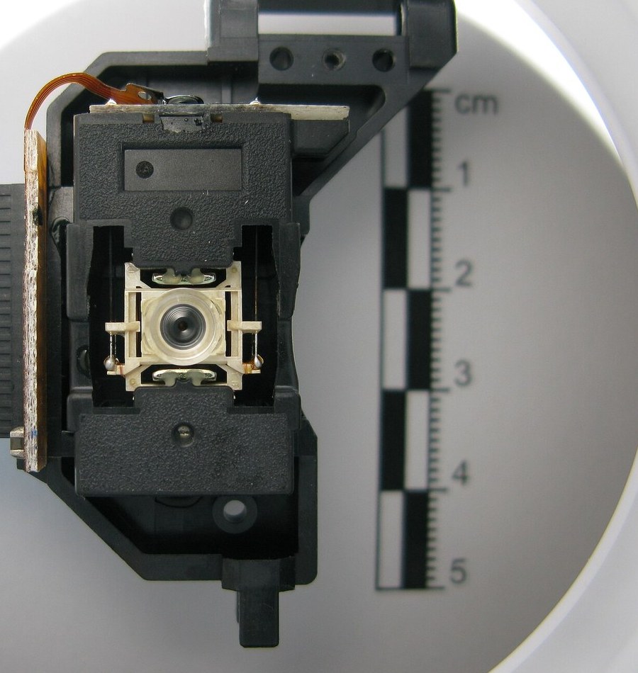
The CD Optical Pickup
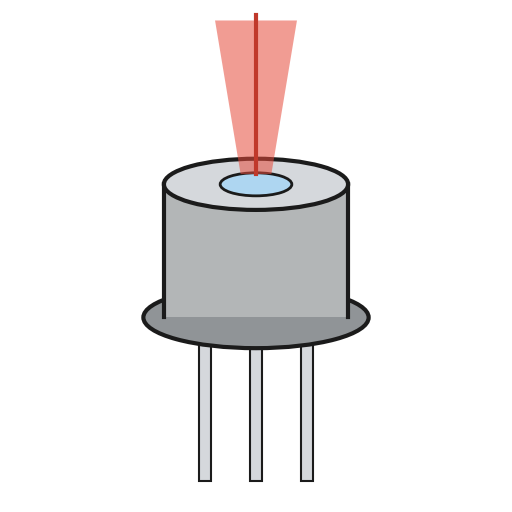
Philips and Sony shipped the compact disc in 1982, and the pickup inside it is the direct descendant of the laser diode in the previous batch. An AlGaAs diode at 780 nanometres, a lens of numerical aperture 0.45, and a spot about two micrometres across scanning a spiral of pits 1.6 micrometres apart. Nothing touches the disc.
Two things about it are cleverer than they look. First, a pit is not read as a shadow. It is a quarter of a wavelength deep INSIDE the polycarbonate, so when the spot straddles a pit edge, half the beam travels an extra half wavelength, and the two halves cancel on the way back. The disc is an interferometer, and the read signal is a destructive interference null.
Second, the lens has to stay within about a micrometre of focus while the disc wobbles axially by hundreds of micrometres. It does that by measuring its own error: a cylindrical lens in the return path makes the spot on a four-quadrant detector an ellipse whose orientation FLIPS through focus, so the difference of the diagonal sums is a signed error signal. That S-shaped curve drives a voice-coil servo — the same actuator as blueprint 6, doing the same job in a different axis.
MEASURABLE, AND PARTLY BUILDABLE. A salvaged pickup plus the laser-diode driver from the previous batch puts the focus-error S-curve on a scope. And the classic measurement needs no pickup at all: a compact disc is a reflection grating with a 1.6 micrometre pitch, so a laser pointer and a ruler measure the track spacing to within a few percent.
མཐོ་རིམ
5 hours
ལམ་སྟོན
1
1
Measure the track pitch with a laser and a ruler
Measure the track pitch with a laser and a ruler
This is the best five minutes in the batch and it needs no pickup at all.
A CD's spiral is a reflection diffraction grating. Shine the laser pointer at the data side at near-normal incidence and catch the reflection on a card a measured distance away, with a hole in the card for the beam to pass through. You will see the specular spot plus first-order spots either side.
Measure the distance L from disc to card and the separation of the first orders. Then `pitch = lambda / sin(theta)`, where `tan(theta)` is half the separation over L. With a 650 nm pointer you should land near 1.6 micrometres.
Repeat with a DVD. The orders spread much wider, because the pitch is 0.74 micrometres. You have just measured the entire generational difference between the two formats with a pointer and a ruler.
གོམ་པ་འདིའི་རྫས་རིགས:
 ཀོམ་པེཀཊ་ཌིསིཀ2 དུམ་བུ།
 ཤོག་སྦོམ།1 སྒྲིལ་ཐུམ།
ལག་ཆས་དགོས་མཁོ:
 ལེ་ཟར་གྱི་སྟོན་ཆས།
 ལེ་ཟར་གྱི་ཉེན་སྲུང་མིག་ཤེལ།
 ཐིག་ཤིང་།
 ཨང་རྟགས་ཚད་འཇལ་ཆས་ ཨིནཅི 6
2
2
Build the quadrant front end
Build the quadrant front end
Salvage a pickup from a dead CD player and identify the flexible cable's pinout from the part number, or use a discrete four-quadrant photodiode with a bare laser diode. Build one transimpedance amplifier PER SEGMENT: this is the circuit from the avalanche-photodiode blueprint, repeated six times, on +9 V and -9 V from two 9 V batteries. Do NOT tie photodiodes together to sum their currents. It saves parts and adds all their capacitances at the summing node, which destroys the RF bandwidth. Sum and difference are taken AFTER the transimpedance stages, always.
Two different jobs from one detector. The RF signal must pass the disc's shortest pits: 3T pits at the 4.3218 MHz channel rate make a 720 kHz fundamental, so the RF path needs well over a megahertz, and its four stages and the summer run on OPA1612s at a low transimpedance (10k). A TL072 would not do for the summer: four inputs give it a noise gain of 5, which would pull its bandwidth down to about 600 kHz. The focus and tracking signals need only tens of kilohertz, so the side-spot stages run on TL072s at high transimpedance (1M) and are much quieter.
Checked in ngspice with behavioural op-amp models and 5 pF per segment (it varies by pickup): about 12 MHz per fast stage and 8.4 MHz through the RF summer; about 76 kHz for the slow stages; and with deliberately unequal test currents, RF = -(A+B+C+D), FE = (A+C) - (B+D) and TE = E - F came out exactly. RV_BAL trims the weight of A+C against B+D, both ways, to null FE with the spot centred.
Drive the laser diode from the constant-current driver of the laser-diode blueprint, at the datasheet current and no more. These diodes are cheap to kill.
KiCanvas བལྟ་མི་ཐོབ་བཞིན...
ཆེད་ལས PCB བཀོད་པ་བལྟ་མི
གོམ་པ་འདིའི་རྫས་རིགས:
 སྒྲ་སྐད་ཉུང་བའི་བཀོལ་སྤྱོད་ཤུགས་སྐྱེད་ཆས (OPA1612)3 དུམ་བུ།
 ཆ་བཞིའི་འོད་ཌཱའི་ཨོཌ1 དུམ་བུ།
 ཨོཔ་ཨེམ་པི་ IC2 དུམ་བུ།
 འགོག་ཆས་ཀྱི་ཚོགས་ཆས།1 དུམ་བུ།
 ཀོན་ཌེན་སར་ཆ་ཚན།1 དུམ་བུ།
 ལེ་སར་ཌ་ཡོཌ1 དུམ་བུ།
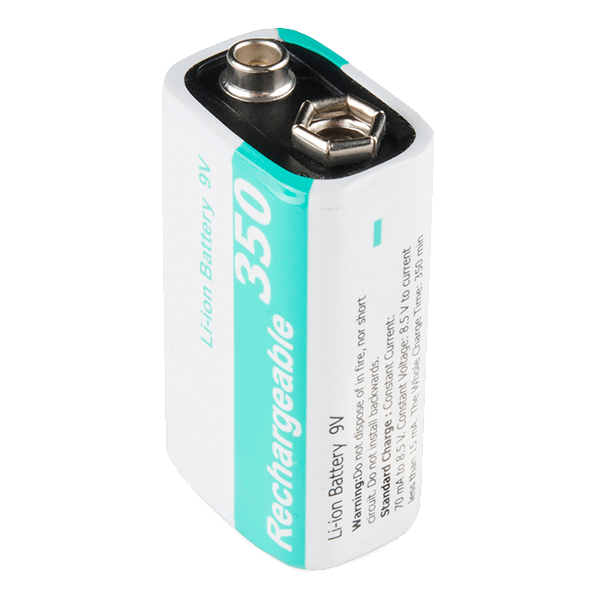 9V Li-ion Rechargeable Battery - 350mAh2 དུམ་བུ།
 གློག་མེའི་འཛིན་ཆས།2 དུམ་བུ།
ལག་ཆས་དགོས་མཁོ:
 Breadboard - Classic
 མཐུད་ཐག་ཆ་ཚན།
 ཨང་རྟགས་ཨོ་སི་ལོ་སི་ཀོབ།ལེ་ཟར་གྱི་ཉེན་སྲུང་མིག་ཤེལ།
3
3
Find the S-curve
Find the S-curve
Mount a CD on a slow geared motor and bring the pickup up to it on a stage you can move by a known amount — a micrometer screw gauge, or a screw with a measured pitch.
Put the focus error output on the oscilloscope and move the objective slowly through focus. You will get the S-curve: zero far away, rising to a peak, crossing zero sharply AT focus, falling to an opposite peak, and dying away again.
Measure two things. The slope through zero, in volts per micrometre — that is the servo's loop gain and it is the number a designer needs. And the capture range, the span over which the signal is monotonic — typically a couple of micrometres.
That limited capture range is why a player sweeps the lens through its whole travel when you insert a disc rather than simply closing the loop. Start outside the capture range and the servo sees almost no error and sits there. The sweep is the whirr you hear.
གོམ་པ་འདིའི་རྫས་རིགས:
ཀོམ་པེཀཊ་ཌིསིཀ1 དུམ་བུ།ལག་ཆས་དགོས་མཁོ:
ཨང་རྟགས་ཨོ་སི་ལོ་སི་ཀོབ། མའི་ཀོ་མི་ཊར།
 ཚད་གཟུང་ཡོད་པའི་ DC འཕྲུལ་འཁོར།
 ཅོག་ཙེའི་གློག་མཁོ་སྤྲོད།
4
4
Spot size, pit depth, and two ways to track
Spot size, pit depth, and two ways to track
Jupyter ཚང་དེབ་མངོན་གསལ་འབད་དོ་…
ལག་ཆས་དགོས་མཁོ:
 ཅོག་ཙེའི་གློག་རིག
5
5
Compendium: the disc that gave up on contact
Compendium: the disc that gave up on contact
WHY IT READS THROUGH THE SUBSTRATE. The beam crosses 1.2 mm of polycarbonate before it reaches the reflective layer, and that is deliberate. At the surface the beam is still about 0.8 mm wide, so a scratch there covers a tiny fraction of it and defocuses into irrelevance. The same particle on the data layer would be fatal. A magnetic drive answers contamination by sealing; the CD answers it with a millimetre of plastic. Both are responses to blueprint 1's exponent, and the optical one is why a CD survives handling and a hard disk does not.
CONSTANT LINEAR VELOCITY. The disc slows from about 500 rpm inside to about 200 outside so the track passes at a constant 1.2 to 1.4 m/s. That keeps the bit rate constant and the pits the same length everywhere, so no capacity is wasted on inner tracks. It also means seeking requires changing spindle speed, which is why CD access is slow and hard-disk access is not.
AGAINST THE LP. The microgroove record is the same object: spinning disc, spiral, transducer on an arm. The stylus touches, so it wears both parts, needs no servo because the groove GUIDES it mechanically, and needs no error correction because noise just sounds like noise. The CD touches nothing and pays with three servos, a channel code and industrial-strength ECC — because a signal read at a distance has no mechanical guide and no graceful degradation. Everything in blueprint 9 exists because of the choice made here.
རྫས་རིགས
10- 3 དུམ་བུ།ས་ཆ་འཛིན
- 1 སྒྲིལ་ཐུམ།ས་ཆ་འཛིན
- ས་ཆ་འཛིན
- 1 དུམ་བུ།ས་ཆ་འཛིན
- 2 དུམ་བུ།ས་ཆ་འཛིན
- ལས་$5.60
- 1 དུམ་བུ།ས་ཆ་འཛིན
- 1 དུམ་བུ།ས་ཆ་འཛིན
- 9V Li-ion Rechargeable Battery - 350mAhཁེ་ཕོགས 10%2 དུམ་བུ།$5.60
- ལས་$1.17
ལག་ཆས་དགོས་མཁོ
11- ས་ཆ་འཛིན
- ས་ཆ་འཛིན
- ས་ཆ་འཛིན
- ས་ཆ་འཛིན
- Breadboard - Classicཁེ་ཕོགས 10%$9.36
- ས་ཆ་འཛིན
- ཨང་རྟགས་ཨོ་སི་ལོ་སི་ཀོབ།ཁེ་ཕོགས 10%Magento Legacy Storeships internationallyས་ཆ་འཛིན
- ས་ཆ་འཛིན
- ཚད་གཟུང་ཡོད་པའི་ DC འཕྲུལ་འཁོར།ཁེ་ཕོགས 10%Magento Legacy Storeships internationallyས་ཆ་འཛིན
- ས་ཆ་འཛིན
- ས་ཆ་འཛིན
ཚོད་དཔག་བསྡོམས
བཟོ་མི་གིས་ཉོ་མི་དེ། གོང་ཚད་མེད་པར་སྟོན་མི་ཅ་ཆས་ཚུ་ཁྱོད་ཀྱིས་ག་ཏེ་ལས་ཉོཝ་ཨིན་ན་དེ་ལས་ཐོབ་ཨིན།
འབྲེལ་ཡོད་བིལུ་པིརིན་ཊི
བིལུ་པིརིན་ཊི་འདི་ཚུ་ཐབས་ལམ་དང་རྫས་རིགས། སྤྱི་ཆོས་བགོ་བཤའ་བྱེད
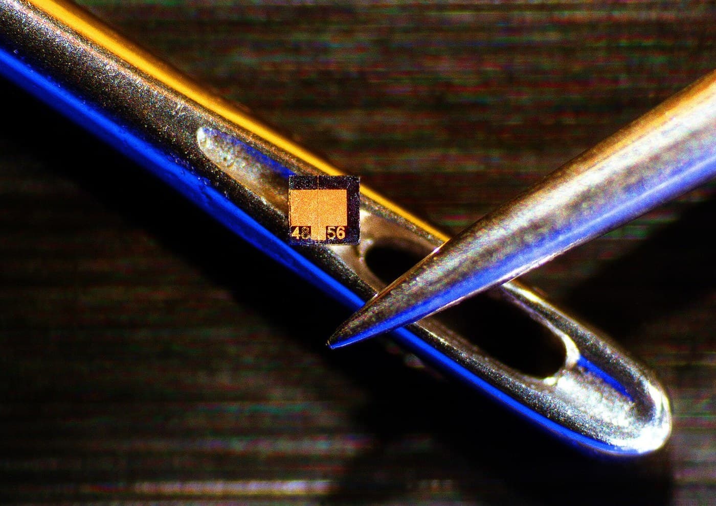
The Semiconductor Laser Diode
Ed གྱིས
གློག་འཕྲུལ
༢
༠
༠
༠
༠
༠
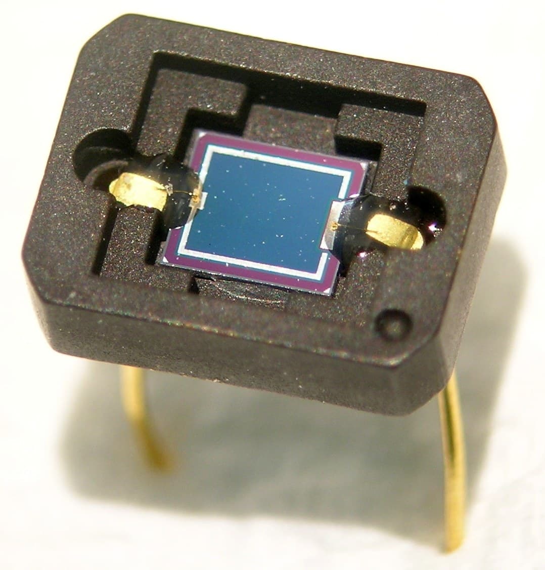
The Avalanche Photodiode Receiver
Ed གྱིས
གློག་འཕྲུལ
༡
༠
༠
༠
༠
༠
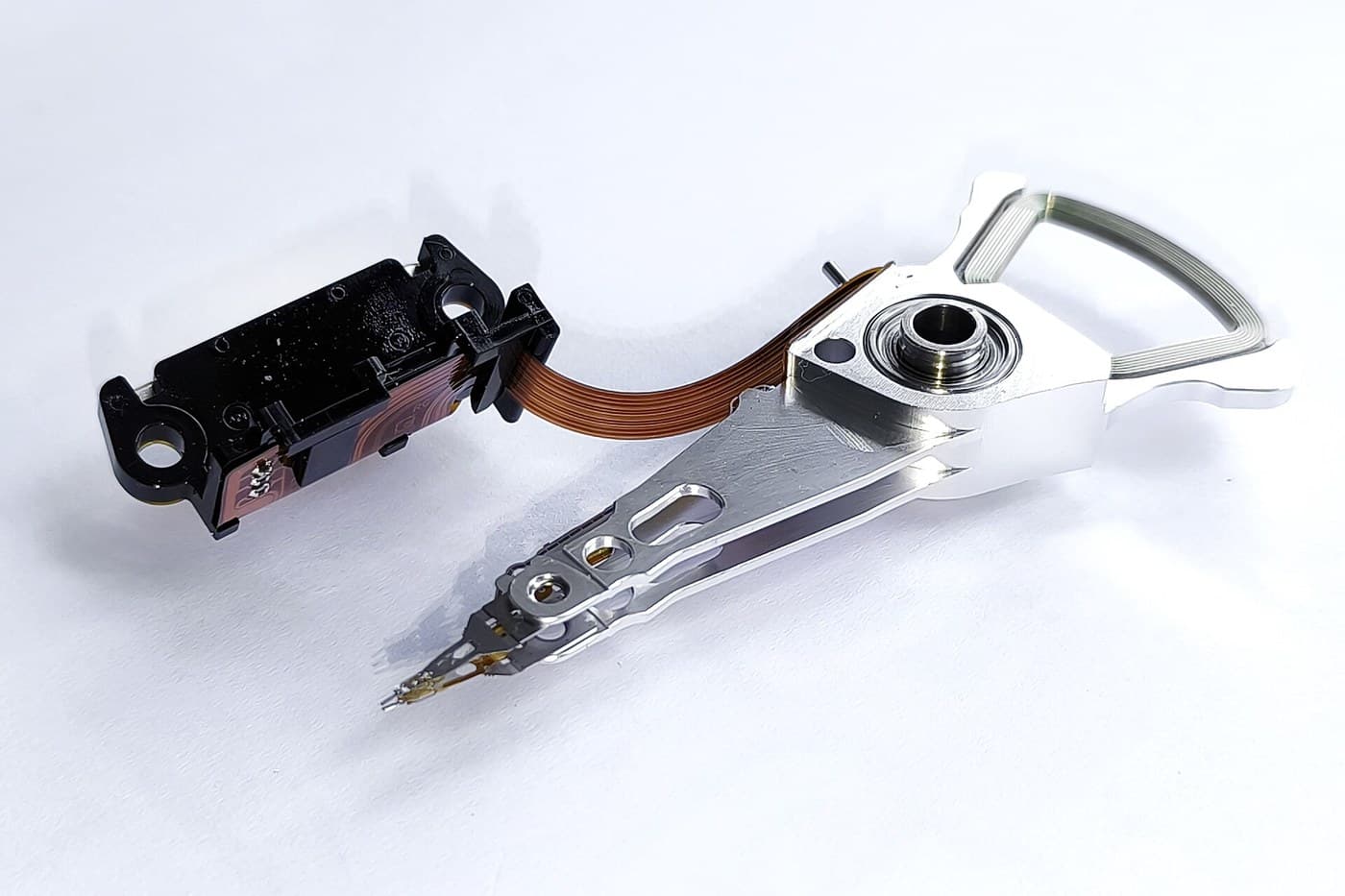
The Voice-Coil Actuator and Track Following
Martin གྱིས
གློག་འཕྲུལ
༥༣
༠
༠
༠
༠
༠
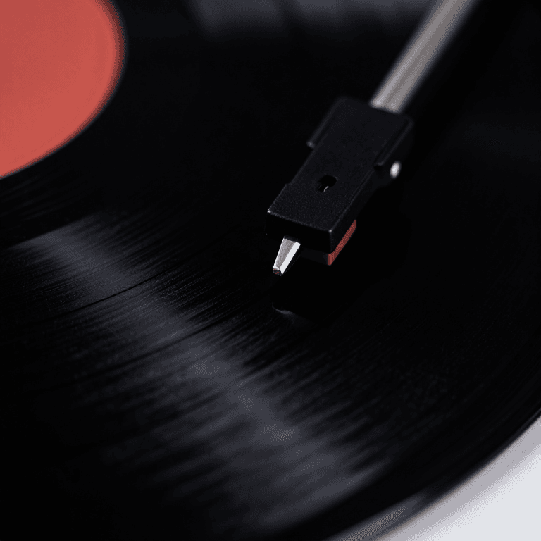
Microgroove LP
Charlie གྱིས
རིག་རྩལ
༣༤
༠
༠
༠
༠
༠
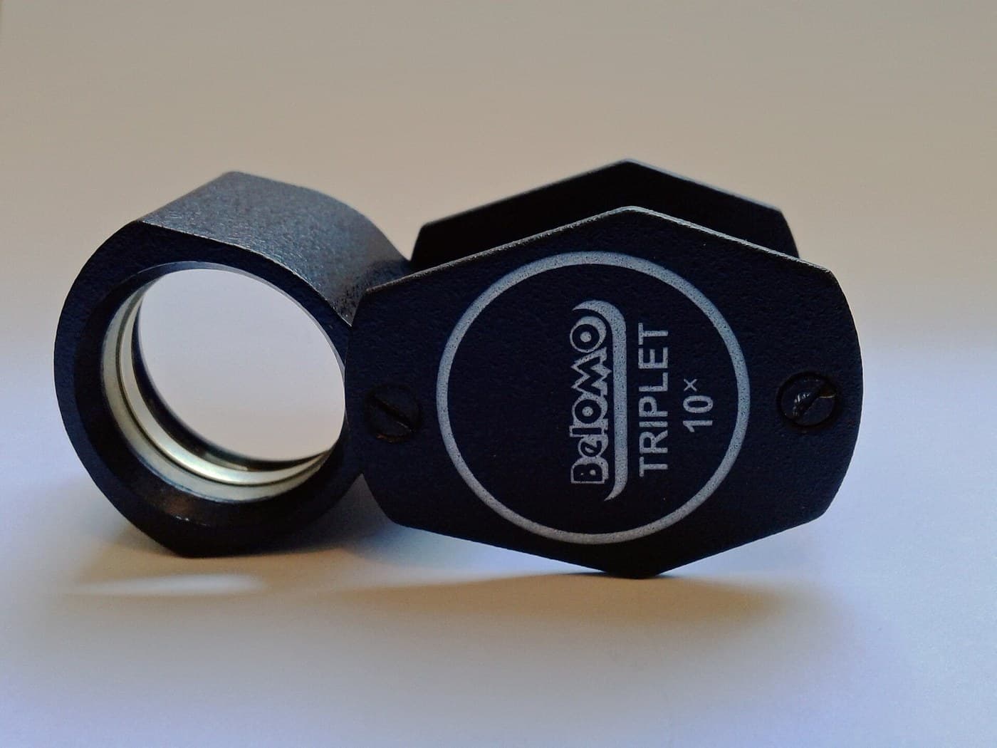
Achromatic Lens
Penny གྱིས
དངོས་ཁམས་རིག
༣༢
༠
༠
༠
༠
༠

Snell's Law — Measure How Light Bends (Laser and Protractor)
Penny གྱིས
དངོས་ཁམས་རིག
༣༩
༠
༠
༠
༠
༠
CC0 སྤྱི་དབང
བིལུ་པིརིན་ཊི་འདི་CC0 འོག་བཀྲམས་ཡོད། ཁྱེད་རང་གིས་ཆོག་མཆན་མ་བཞེས་པར་ཕབ་ལེན་དང་བཟོ་བཅོས། བགོ་བཤའ། དགོས་མཁོ་གང་ལའང་བཀོལ་སྤྱོད་བྱས་ཆོག
བཟོ་མཁན་ལ་རྒྱབ་སྐྱོར་བྱེད་པའི་ཆེད་ཁོང་ཚོའི་བིལུ་པིརིན་ཊི་བརྒྱུད་ཐོན་སྐྱེད་ཉོ། བཟོ་མཁན་གྱིས བཟོ་མཁན་གྱི་ཁེ་ཕོགས ཚོང་པས་གཏན་འཁེལ་བྱས་པ། ཡང་ན་བིལུ་པིརིན་ཊི་འདིའི་པར་གསར་བཟོས་ཏེ་ཁྱེད་རང་གི་བིལུ་པིརིན་ཊི་ནང་མཐུད་སྦྲེལ་བྱས་ཏེ་ཡོང་སྒོ་བགོ་བཤའ་བྱེད།