སྒྱུ་རྩལ
མཛེས་སྡུག་དང་བདེ་ཐང
བཟོ་རིག
རིག་གནས་དང་ལོ་རྒྱུས
དགའ་སྟོན
ཁོར་ཡུག
ཟས་དང་བཏུང་རྫས
ཕྱིར་འཕྲུལ་རིག
ཚན་རིག
རྩེད་འགྲན
རིག་རྩལ
གྱོན་རུང
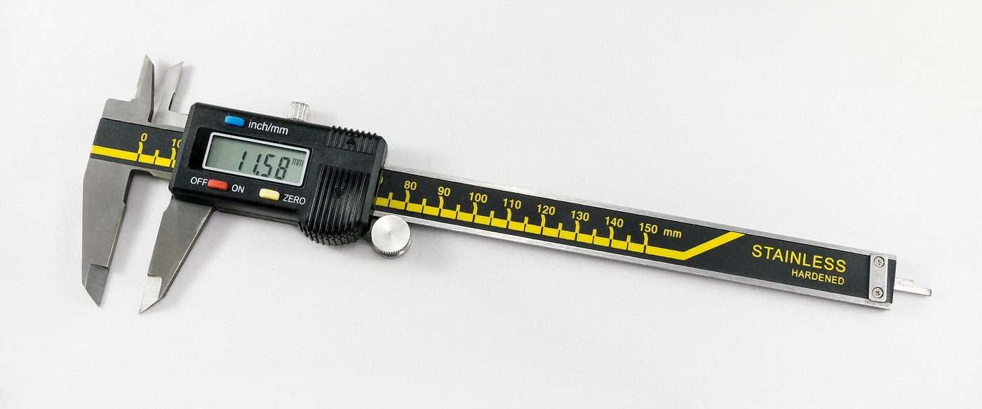


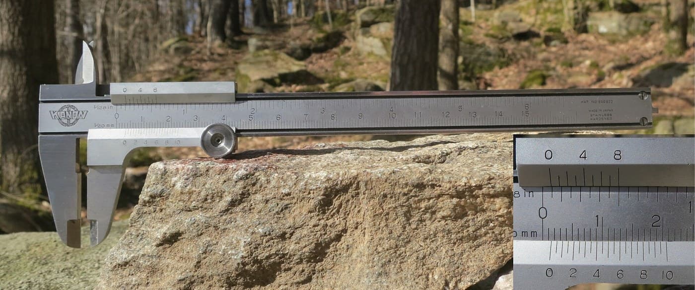
Digital Caliper: Capacitive Scale and Slider with Two-Chip Electronics (Baxter and Buehler, Starrett, 1986)
A six-inch caliper that reads out on a display. Under the slide, a strip of etched copper bars runs along the beam. Electrodes on the slider pass a signal through the bars by capacitance, and the slider's electronics count the bars crossed and work out the position in between.
Result: a digital caliper reading in inches or millimetres, repeatable to a ten-thousandth of an inch, with floating zero, peak hold and high/low limits. It runs on two 1.5 V cells at 10-50 microamps.
Source: L. K. Baxter and R. J. Buehler (L. S. Starrett Co.), US Patent 4,586,260 (1986). Unknown: the metal of the beam, slide and rod, their dimensions, the processor's program, and how the chips and display are made. Ours: the etchant, photoresist and glue. Picture: Wikimedia Commons.
མཐོ་རིམ
2 days
ལམ་སྟོན
1
1
Etch the scale
Etch the scale
Etch the scale pattern onto a strip of copper-clad epoxy fibreglass with photoresist and etchant. Each copper bar is 0.40 inch long, with a wider centre 0.12 inch long and two ends 0.14 inch long. Space the bars on 0.05 inch centres: the centres sit 0.004 inch apart, the ends 0.025 inch apart. Run the pattern the full length of the scale. Ours: dry film resist and ferric chloride.
གོམ་པ་འདིའི་རྫས་རིགས:
 PCB ལེབ་སྟོང་པ། (ཟངས་གཡོགཔ)1 strip, length of the beam
ལག་ཆས་དགོས་མཁོ:
 སྐམ་པའི་ཤོག་ལེབ་འོད་འགོག་རྫས།
 ལྕགས་ཀྱི་ཀུ་ལོ་རའིཌི་ཁུ་བ།
 རྫས་སྦྱོར་བཟོད་ཐུབ་པའི་ལག་ཤུབས།
2
2
Fix the scale into the beam
Fix the scale into the beam
The beam is a metal bar with the fixed outside and inside jaws at one end, a wide shallow channel in its face and a second channel along its back. Fix the scale permanently into the face channel, copper up. The patent allows etching before or after this step. Not given: the metal, the dimensions and how the scale is fixed. Ours: epoxy.
གོམ་པ་འདིའི་རྫས་རིགས:
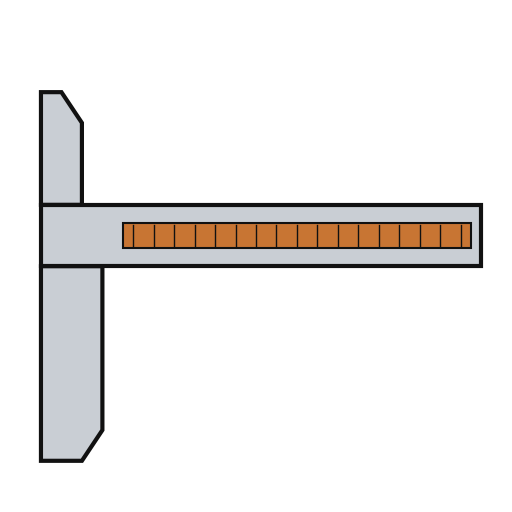 ཀེ་ལི་པར་གྱི་ཤིང་དོང་།1 with integral jaws
 ཆ་ཤས་གཉིས་ལྡན་གྱི་ཨི་པོག་སི་སྦྱོར་རྒྱུ། (མགྱོགས་པར་སྲ་བ།)1 a little
ལག་ཆས་དགོས་མཁོ:
 མ་ཤེས་པའི་ཚད།
3
3
Fit the parts to the circuit
Fit the parts to the circuit
The circuit is one folded piece: a double-sided slider board joined by a flexible hinge to a circuit board. Its bottom face has two pickup electrodes, 0.750 x 0.110 inch and 0.0625 inch apart. On each side of them is an interdigitated transmitter array: fingers 0.115 inch long on 0.025 inch spacing, opening to 0.0375 inch at the centre. On the circuit board, solder or wire-bond the two chips: an NEC uPD7503 3 V processor (768 bits RAM, 2 kB ROM) and a CMOS gate array. Then fit the LCD, the 100 kHz crystal, the integrating capacitor and the MODE and SET buttons. Not given: the processor's program. Ours: a capacitor from a kit.
གོམ་པ་འདིའི་རྫས་རིགས:
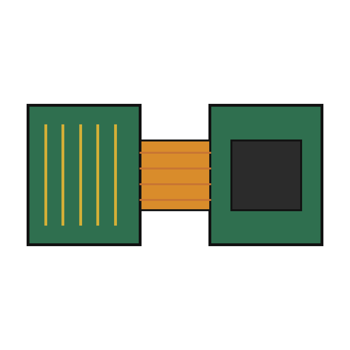 སྲ་བ་དང་ལྕུག་ཅན་གྱི་འཁོར་ལམ་པང་ལེབ།1 slider board + circuit board
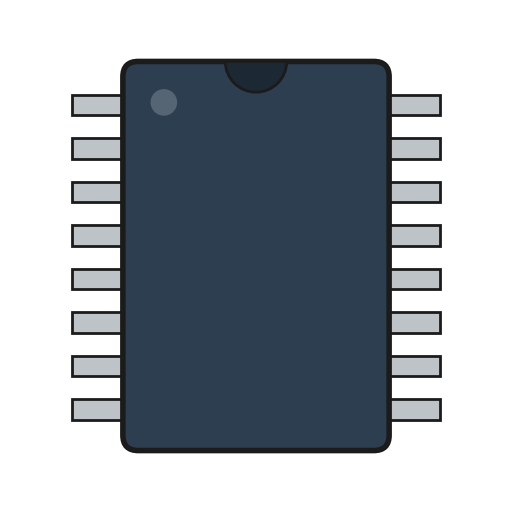 IC2 uPD7503 CPU, CMOS gate array
 ཆ་ཤས་ཅན་གྱི་ཤེལ་རྡོ་ཆུ་ཅན་གསལ་སྟོན།1 5 digits
 ཀྭརཙ་ ཤེལ་རྡོ།1 100 kHz
 ཀོན་ཌེན་སར་ཆ་ཚན།1 one integrating capacitor
 གནོན་ཐེབས།2 MODE, SET
 ཞ་སྦྱར་རྫས་ཀྱི་སྐུད་པ1 a little
ལག་ཆས་དགོས་མཁོ:
 ཞ་བཏབ་ནིའི་ལྕགས།
4
4
Build the slide
Build the slide
The slide frame wraps the back and edges of the beam and carries the movable jaws. Fix it to the depth rod, which runs in the back channel of the beam; the rod's free end is the depth gauge. Put the moulded plastic housing between the frame ends. Fasten two metal wear strips under the slider board, one on each side of the scale. They ride on the beam and connect the board's copper to it. Not given: the metal and sizes.
གོམ་པ་འདིའི་རྫས་རིགས:
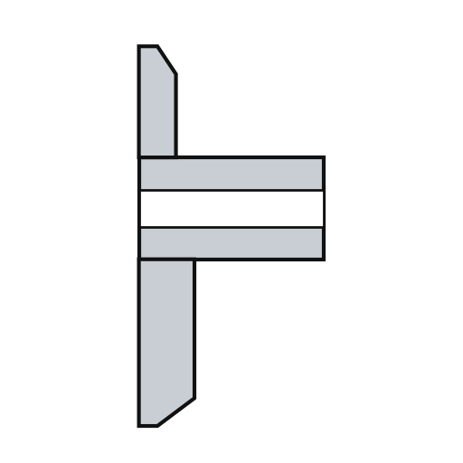 བཤུད་ཆས་ཀྱི་སྒྲོམ།1 with jaws
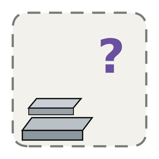 མ་ཤེས་པའི་ལྕགས་རིགས།1 depth rod and two wear strips
 བཤུད་ཆས་ཀྱི་ཤུན་པ།1 དུམ་བུ།
ལག་ཆས་དགོས་མཁོ:
མ་ཤེས་པའི་ཚད། དག་ཞིབ་ཀྱི་སི་ཀུརུ་ཌརཱའི་བར་ཆ་ཚང་
5
5
Assemble and check
Assemble and check
Fold the circuit into the housing recess, slider board facing the scale, and screw it to the frame. The electrodes must lie parallel to the scale bars at every point of travel. Put the two 1.5 V cells (the patent says 'zinc oxide') in the battery pockets of the circuit. The display shows five digits, a ten-thousandths bar graph, a minus sign and 'mm', plus PEAK, LOW, HIGH and LIMIT. Ours: check the reading against a vernier caliper.
གོམ་པ་འདིའི་རྫས་རིགས:
 འཕྲུལ་གྱི་སི་ཀུརུ།2 དུམ་བུ།
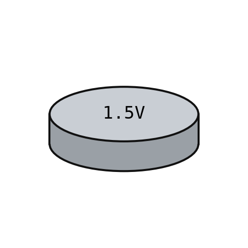 ཝོལཊི་ ༡.༥ གི་ མཐེབ་གློག་རྫས།2 དུམ་བུ།
ལག་ཆས་དགོས་མཁོ:
དག་ཞིབ་ཀྱི་སི་ཀུརུ་ཌརཱའི་བར་ཆ་ཚང་ བར་ནི་ཡར་གྱི་འཇལ་ཆས།
རྫས་རིགས
15- 1 strip, length of the beamས་ཆ་འཛིན
- 1 with integral jawsས་ཆ་འཛིན
- ས་ཆ་འཛིན
- 1 slider board + circuit boardས་ཆ་འཛིན
- 2 uPD7503 CPU, CMOS gate arrayས་ཆ་འཛིན
- 1 5 digitsས་ཆ་འཛིན
- 1 100 kHzས་ཆ་འཛིན
- 1 one integrating capacitorས་ཆ་འཛིན
- ས་ཆ་འཛིན
- 1 a littleས་ཆ་འཛིན
- 1 with jawsས་ཆ་འཛིན
- 1 depth rod and two wear stripsས་ཆ་འཛིན
- 1 དུམ་བུ།ས་ཆ་འཛིན
- 2 དུམ་བུ།ས་ཆ་འཛིན
- 2 དུམ་བུ།ས་ཆ་འཛིན
ལག་ཆས་དགོས་མཁོ
7- ས་ཆ་འཛིན
- ས་ཆ་འཛིན
- ས་ཆ་འཛིན
- ས་ཆ་འཛིན
- 2 vendors sell this, none ship to you yetས་ཆ་འཛིན
- ས་ཆ་འཛིན
མཐུད་སྦྲེལ་བིལུ་པིརིན་ཊི་རྫས་རིགས

བིལུ་པིརིན་ཊི་འདི་གིས་བཟོ་མི

འབྲེལ་ཡོད་བིལུ་པིརིན་ཊི
བིལུ་པིརིན་ཊི་འདི་ཚུ་ཐབས་ལམ་དང་རྫས་རིགས། སྤྱི་ཆོས་བགོ་བཤའ་བྱེད
CC0 སྤྱི་དབང
བིལུ་པིརིན་ཊི་འདི་CC0 འོག་བཀྲམས་ཡོད། ཁྱེད་རང་གིས་ཆོག་མཆན་མ་བཞེས་པར་ཕབ་ལེན་དང་བཟོ་བཅོས། བགོ་བཤའ། དགོས་མཁོ་གང་ལའང་བཀོལ་སྤྱོད་བྱས་ཆོག
བཟོ་མཁན་ལ་རྒྱབ་སྐྱོར་བྱེད་པའི་ཆེད་ཁོང་ཚོའི་བིལུ་པིརིན་ཊི་བརྒྱུད་ཐོན་སྐྱེད་ཉོ། བཟོ་མཁན་གྱིས བཟོ་མཁན་གྱི་ཁེ་ཕོགས ཚོང་པས་གཏན་འཁེལ་བྱས་པ། ཡང་ན་བིལུ་པིརིན་ཊི་འདིའི་པར་གསར་བཟོས་ཏེ་ཁྱེད་རང་གི་བིལུ་པིརིན་ཊི་ནང་མཐུད་སྦྲེལ་བྱས་ཏེ་ཡོང་སྒོ་བགོ་བཤའ་བྱེད།