སྒྱུ་རྩལ
མཛེས་སྡུག་དང་བདེ་ཐང
བཟོ་རིག
རིག་གནས་དང་ལོ་རྒྱུས
དགའ་སྟོན
ཁོར་ཡུག
ཟས་དང་བཏུང་རྫས
ཕྱིར་འཕྲུལ་རིག
ཚན་རིག
རྩེད་འགྲན
རིག་རྩལ
གྱོན་རུང
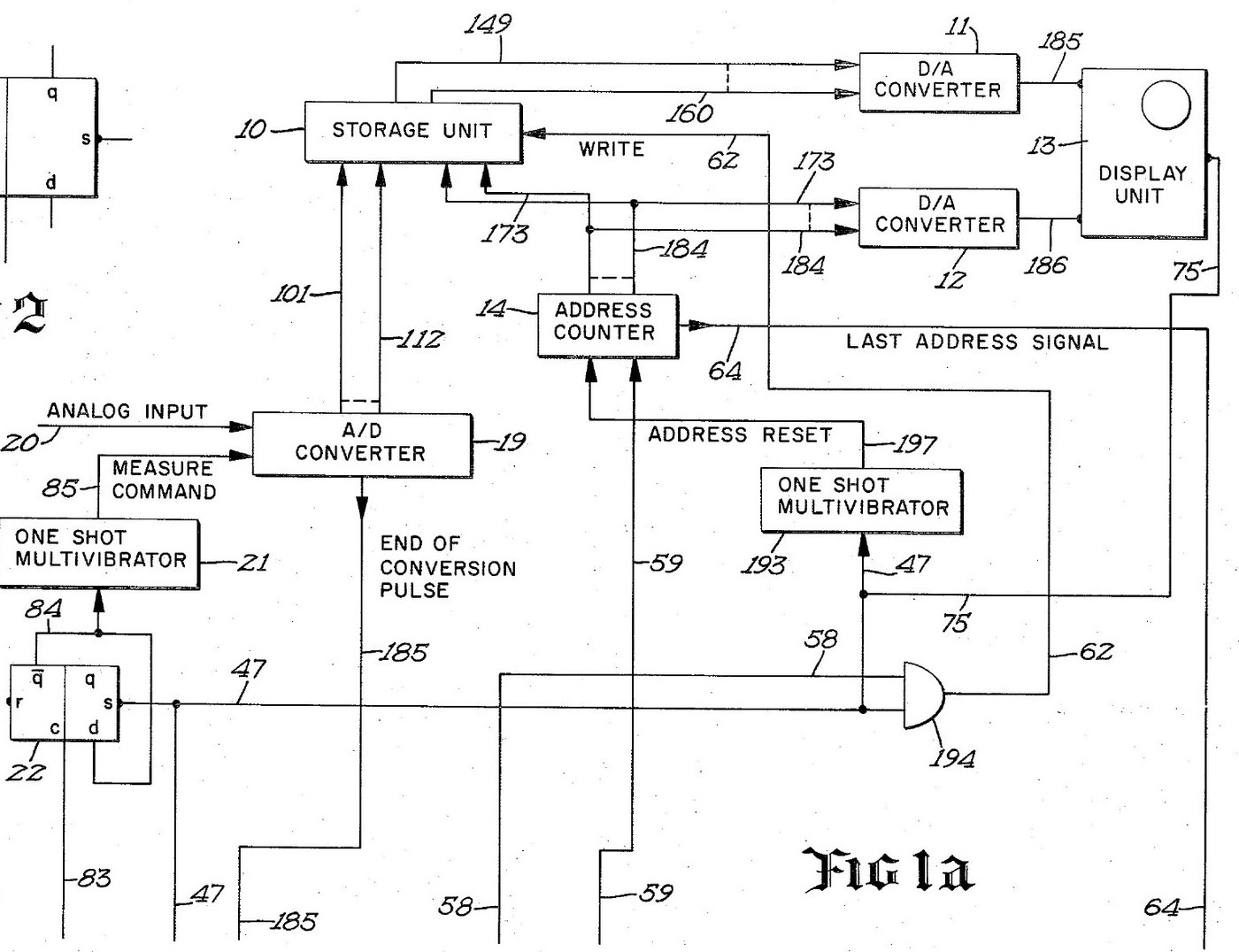


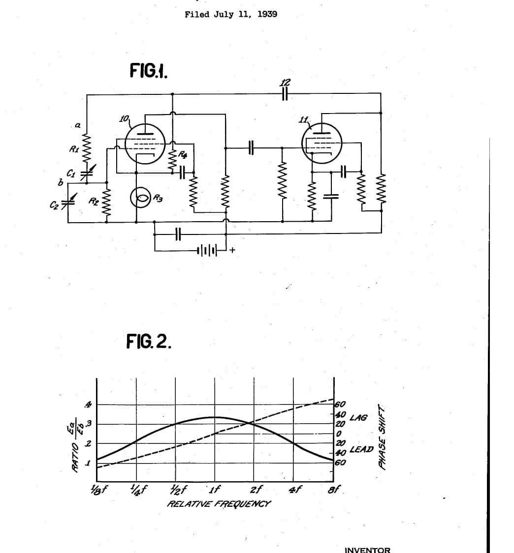
Digital Oscilloscope: Waveform Stored in Memory and Shown on a CRT (Schumann, Nicolet, US 3,816,815, 1974)
An oscilloscope with a memory. After a trigger, an analog-to-digital converter measures the input at regular intervals and writes each reading into its own memory register, replacing the old one. The screen then shows the memory: each register's number sets the beam's height, its address sets the beam's place across. The last waveform can be held on the screen as long as you like.
Result: a digital storage oscilloscope with 4,096 points of 12 bits, refresh and hold modes and single-shot capture.
Source: R. W. Schumann (Nicolet), US 3,816,815 (1974). Unknown: sample rate, bandwidth, voltages and the parts used. Picture: the patent drawing.
ཆེས་མཁས་པ
Unknown
ལམ་སྟོན
1
1
Sample and convert the input
Sample and convert the input
Bring the analog input to an analog-to-digital converter, through a BNC socket. A sampling oscillator, divided by four by two flip-flops so the first reading comes soon after the sweep starts, fires a one-shot multivibrator that gives the converter its measure command. The converter holds each 12-bit result on its output lines and signals the end of each conversion. Ours: a BNC socket. Not given: the sample rate.
གོམ་པ་འདིའི་རྫས་རིགས:
 རྒྱུན་ཆགས་ལས་ཨང་ཅན་ལུ་སྒྱུར་ཆས1 12-bit converter
 དུས་ཚོད་ཀྱི་ འགུལ་སྐྱོད་ཆས།1 sampling oscillator
 ལོ་ཇིཀ་ IC སྣ་འདྲེས་ཆ་ཚང་།1 flip-flops, one-shots, gates
 ཀིང་གཅིག་མཐུད་ཆས་ཆ་ཚང (BNC / SO-239)1 input socket
ལག་ཆས་དགོས་མཁོ:
 ཞ་བཏབ་ནིའི་ལྕགས།
 ལྕགས་སྐུད་ཀྱི་ཤུབས་བཤུས་ཆས།
2
2
Store each reading in memory
Store each reading in memory
Wire an integrated-circuit memory of 4,096 registers, 12 bits each, that can be read without changing it. A 12-bit address counter picks the register. On each write command the register at the current address takes the last reading from the converter, and the counter steps on. When the sweep starts, a one-shot resets the counter to zero. When it reaches the last address, its last-address signal ends the sweep.
གོམ་པ་འདིའི་རྫས་རིགས:
 ཚོགས་བསྡོམས་གློག་ལམ་གྱི་ དྲན་ཚད།1 4,096 x 12-bit store
ལག་ཆས་དགོས་མཁོ:
ཞ་བཏབ་ནིའི་ལྕགས།ལྕགས་སྐུད་ཀྱི་ཤུབས་བཤུས་ཆས།3
3
Drive the CRT from the memory
Drive the CRT from the memory
Feed the addressed register's number to one digital-to-analog converter and the address to a second. Their outputs drive the vertical and horizontal deflection plates of a cathode-ray tube, so the beam always stands at the height of the stored reading and at the place of its address. Wire the sweep line to the tube's intensifier, to brighten the trace while a waveform is being taken.
གོམ་པ་འདིའི་རྫས་རིགས:
 ཨང་རྟགས་ལས་ ཨེ་ན་ལོག་ལུ་ བསྒྱུར་ཆས།2 vertical and horizontal
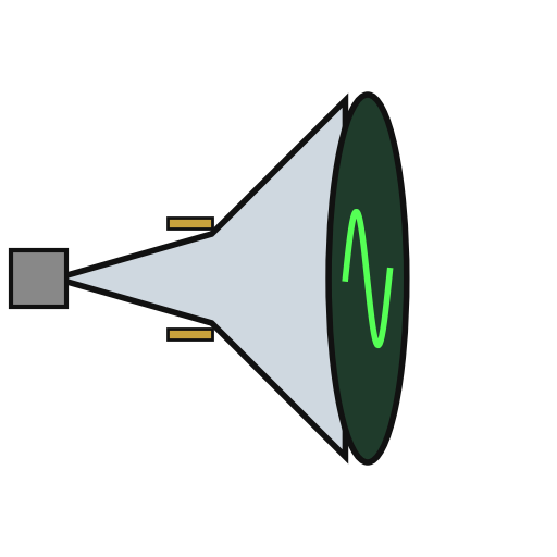 ཀེ་ཐོཌ་འོད་ཟེར་ དོང་པོ།1 display tube
ལག་ཆས་དགོས་མཁོ:
ཞ་བཏབ་ནིའི་ལྕགས།ལྕགས་སྐུད་ཀྱི་ཤུབས་བཤུས་ཆས།4
4
Wire the trigger and the modes
Wire the trigger and the modes
A trigger input, usually from the leading edge of the input waveform, starts the sweep, once a measure flip-flop has armed it. Put a two-position mode switch on the face: MODE I and MODE II. Add a push button in the probe, a switch on the panel and an external initiate input; each goes through a flip-flop that removes contact bounce. Two more oscillators step the memory round to refresh the display between waveforms. Mount it all in a case with its supply. Ours: toggle switches, an aluminium case, a DC supply. Not given: the supply voltages.
གོམ་པ་འདིའི་རྫས་རིགས:
དུས་ཚོད་ཀྱི་ འགུལ་སྐྱོད་ཆས།2 display sequencing oscillators འཕར་སྒུལ་སྒོ་ལྕགས།2 mode and panel switches
 གནོན་ཐེབས།1 probe switch
 ཨ་ལུ་མི་ནིཡམ་གྱི་སྒྲོམ།1 case
ལག་ཆས་དགོས་མཁོ:
 ཐད་རྒྱུན་གློག་ཁུངས།
 འཁོད་བཞག་ཕུག་འཕྲུལ།ཞ་བཏབ་ནིའི་ལྕགས།
5
5
Capture and hold a waveform
Capture and hold a waveform
In MODE I, refresh: each new triggered waveform replaces the last on the screen. Press the probe or panel switch to hold: new waveforms are rejected and the last one stays on the screen. In MODE II the screen normally holds; on command, it takes the first waveform after the command, stores it and shows it steadily. Test it with a known signal.
ལག་ཆས་དགོས་མཁོ:
 རླབས་བཟོ་འཕྲུལ་ཆས།
རྫས་རིགས
10- 1 12-bit converterས་ཆ་འཛིན
- 2 display sequencing oscillatorsས་ཆ་འཛིན
- 1 flip-flops, one-shots, gatesས་ཆ་འཛིན
- 1 input socketས་ཆ་འཛིན
- 1 4,096 x 12-bit storeས་ཆ་འཛིན
- 2 vertical and horizontalས་ཆ་འཛིན
- 1 display tubeས་ཆ་འཛིན
- ས་ཆ་འཛིན
- ས་ཆ་འཛིན
- 1 caseས་ཆ་འཛིན
ལག་ཆས་དགོས་མཁོ
5- 2 vendors sell this, none ship to you yetས་ཆ་འཛིན
- ས་ཆ་འཛིན
- ས་ཆ་འཛིན
- ས་ཆ་འཛིན
- ས་ཆ་འཛིན
བིལུ་པིརིན་ཊི་འདི་གིས་བཟོ་མི

འབྲེལ་ཡོད་བིལུ་པིརིན་ཊི
བིལུ་པིརིན་ཊི་འདི་ཚུ་ཐབས་ལམ་དང་རྫས་རིགས། སྤྱི་ཆོས་བགོ་བཤའ་བྱེད
CC0 སྤྱི་དབང
བིལུ་པིརིན་ཊི་འདི་CC0 འོག་བཀྲམས་ཡོད། ཁྱེད་རང་གིས་ཆོག་མཆན་མ་བཞེས་པར་ཕབ་ལེན་དང་བཟོ་བཅོས། བགོ་བཤའ། དགོས་མཁོ་གང་ལའང་བཀོལ་སྤྱོད་བྱས་ཆོག
བཟོ་མཁན་ལ་རྒྱབ་སྐྱོར་བྱེད་པའི་ཆེད་ཁོང་ཚོའི་བིལུ་པིརིན་ཊི་བརྒྱུད་ཐོན་སྐྱེད་ཉོ། བཟོ་མཁན་གྱིས བཟོ་མཁན་གྱི་ཁེ་ཕོགས ཚོང་པས་གཏན་འཁེལ་བྱས་པ། ཡང་ན་བིལུ་པིརིན་ཊི་འདིའི་པར་གསར་བཟོས་ཏེ་ཁྱེད་རང་གི་བིལུ་པིརིན་ཊི་ནང་མཐུད་སྦྲེལ་བྱས་ཏེ་ཡོང་སྒོ་བགོ་བཤའ་བྱེད།