Driving a Servo Motor — SIK Circuit 8
ལམ་སྟོན
Parts & Introduction
Parts & Introduction
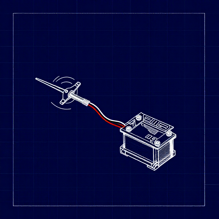
A servo motor can be precisely positioned between 0 and 180 degrees. Unlike a regular motor that just spins, servos hold their position — making them perfect for robotics, pan/tilt mechanisms, and control surfaces. This experiment introduces the Servo library.
Parts Needed
- 1x Arduino Uno + USB cable
- 1x Breadboard
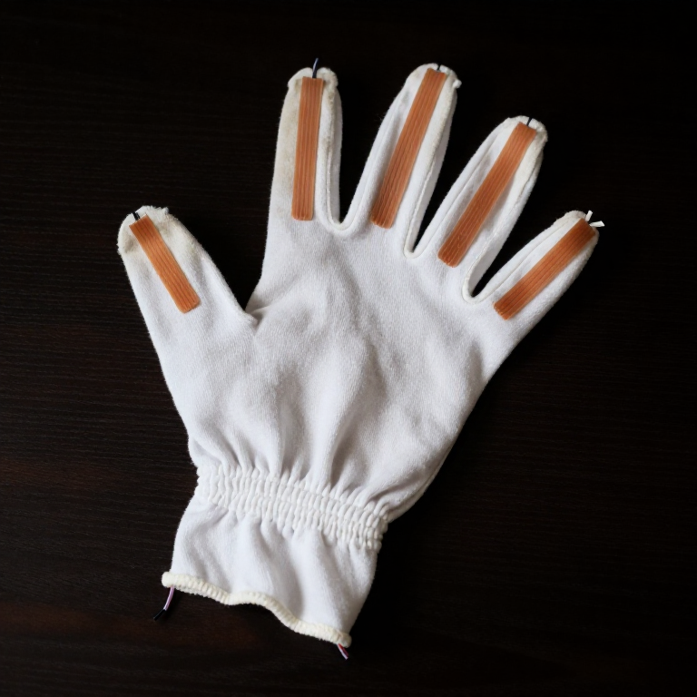
- 1x Servo Motor (with 3-pin header)
- 8x Jumper Wires
The servo has three wires: Red (power), Black (ground), White (signal).
གོམ་པ་འདིའི་རྫས་རིགས:
 SparkFun Inventors Kit - V3.21 kit
 Jumper Wires3 pieces
ལག་ཆས་དགོས་མཁོ:
Hardware Hookup
Hardware Hookup
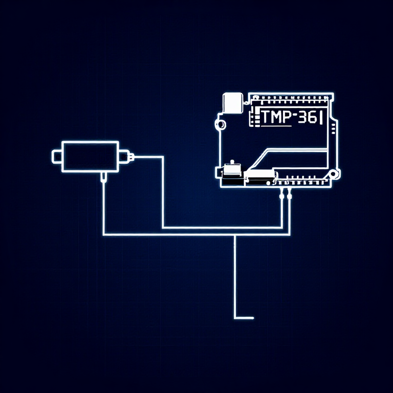
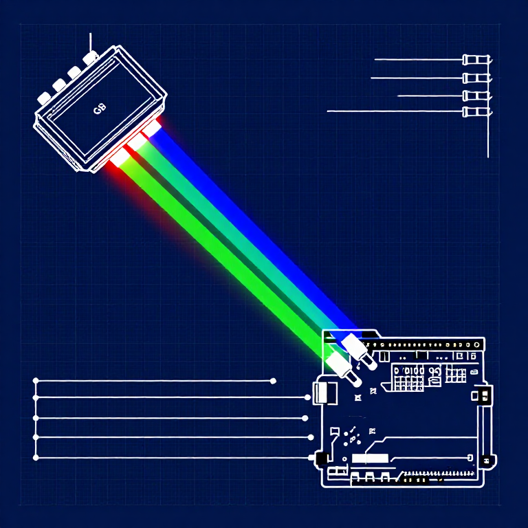
Wiring Instructions
- Connect 3 jumper wires to the servo's female 3-pin header for breadboarding.
- Connect the Red wire to 5V.
- Connect the Black wire to GND.
- Connect the White wire (signal) to Digital Pin 9.
Power Note: Servos draw significant current. If the servo twitches and the Arduino resets, use a wall adapter instead of USB power, or power the servo from a separate 5V supply.
གོམ་པ་འདིའི་རྫས་རིགས:
Jumper Wires3 piecesArduino Code
Arduino Code
Open the Arduino IDE and upload the following sketch to your Arduino board.
གོམ་པ་འདིའི་རྫས་རིགས:
ལག་ཆས་དགོས་མཁོ:
Test & Experiment
Test & Experiment
What You Should See
The servo quickly moves to 90°, 180°, and 0° (1 second each), then slowly sweeps from 0° to 180° and back.
Troubleshooting
- Servo not moving: Even with colored wires, it's easy to plug a servo in backwards. Check connections.
- Twitching/resetting: The servo draws too much power from USB. Use a wall adapter or separate power supply.
Experiments to Try
- Add a potentiometer (from Circuit 2) to control servo position with a knob.
- Change the step size and delay to experiment with speed and smoothness.
- Build a simple pan/tilt mechanism with two servos.
རྫས་རིགས
5- $105.00
Related blueprints
Other builds that share materials, tools, or techniques with this one.

CC0 སྤྱི་དབང
བིལུ་པིརིན་ཊི་འདི་CC0 འོག་བཀྲམས་ཡོད། ཁྱེད་རང་གིས་ཆོག་མཆན་མ་བཞེས་པར་ཕབ་ལེན་དང་བཟོ་བཅོས། བགོ་བཤའ། དགོས་མཁོ་གང་ལའང་བཀོལ་སྤྱོད་བྱས་ཆོག
བཟོ་མཁན་ལ་རྒྱབ་སྐྱོར་བྱེད་པའི་ཆེད་ཁོང་ཚོའི་བིལུ་པིརིན་ཊི་བརྒྱུད་ཐོན་སྐྱེད་ཉོ། བཟོ་མཁན་གྱིས བཟོ་མཁན་གྱི་ཁེ་ཕོགས ཚོང་པས་གཏན་འཁེལ་བྱས་པ། ཡང་ན་བིལུ་པིརིན་ཊི་འདིའི་པར་གསར་བཟོས་ཏེ་ཁྱེད་རང་གི་བིལུ་པིརིན་ཊི་ནང་མཐུད་སྦྲེལ་བྱས་ཏེ་ཡོང་སྒོ་བགོ་བཤའ་བྱེད།