སྒྱུ་རྩལ
མཛེས་སྡུག་དང་བདེ་ཐང
བཟོ་རིག
རིག་གནས་དང་ལོ་རྒྱུས
དགའ་སྟོན
ཁོར་ཡུག
ཟས་དང་བཏུང་རྫས
ཕྱིར་འཕྲུལ་རིག
ཚན་རིག
རྩེད་འགྲན
རིག་རྩལ
གྱོན་རུང
Youblob (generated from this blueprint's notebook) · CC0


The Time-Delay Relay: Switching a Set Time Later
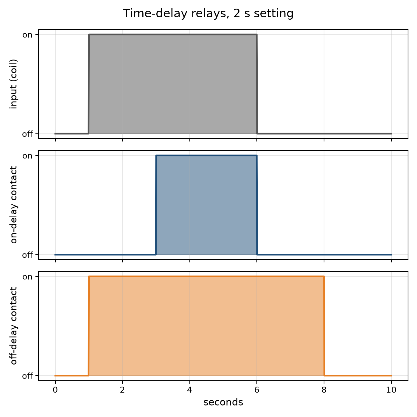
Many control jobs need a pause: start the motor, wait until it is up to speed, then load it; stop the burner, then run the fan a little longer to clear the heat; light the stairway, and switch it off a few minutes later. The time-delay relay does it. An on-delay closes its contact a set time after it is energised; an off-delay keeps its contact closed a set time after it is de-energised.
The earliest timed their delay with a dashpot — a piston pushing air or oil through a small adjustable hole — or with a bimetal warmed by a heater. Electronic relays charge a capacitor through a resistor and switch when it reaches a threshold.
This rung works out an RC delay and why capacitor tolerance and leakage limit it, draws on- and off-delay timing, and builds an on-delay relay with a 555 timer.
འགོ་བཙུགས
About 3 hours
ལམ་སྟོན
1
1
The RC delay and its limits
The RC delay and its limits
Jupyter ཚང་དེབ་མངོན་གསལ་འབད་དོ་…
2
2
Build a 555 on-delay relay
Build a 555 on-delay relay
On a breadboard wire a 555 as a monostable from a 9–12 V supply: pins 4 and 8 to the supply, pin 1 to 0 V, a resistor R from the supply to pins 6 and 7 joined, a capacitor C from pins 6 and 7 to 0 V, 10 nF from pin 5 to 0 V, and pin 2 (trigger) held high through 10 kΩ with a push button to 0 V.
Pin 3 goes high for 1.1 RC after the button is pressed. Drive an NPN transistor from pin 3 through 1 kΩ, with the relay coil between the supply and the collector and a diode across the coil, reversed, to catch the coil's kick. Wire an LED through the relay's contact.
Time the relay with a stopwatch for three values of R. Plot delay against R: a straight line whose slope is 1.1 C. Swap in a second capacitor of the same marked value and watch the delay change — its tolerance.
གོམ་པ་འདིའི་རྫས་རིགས:
 NE555 དུས་འཛིན་ IC1 དུམ་བུ།
 NPN ཊུརེན་སིསི་ཊར།1 དུམ་བུ།
 SPDT རི་ལེ1 དུམ་བུ།
 ཌའི་ཨོཌ།1 དུམ་བུ།
 ཀོན་ཌེན་སར་ཆ་ཚན།1 དུམ་བུ།
 འགོག་ཆས་ཀྱི་ཚོགས་ཆས།1 དུམ་བུ།
 གནོན་ཐེབས།1 དུམ་བུ།
 མི་ལི་མི་ཊར ༥ གི LED1 དུམ་བུ།
 བེརེཌ་བོཌ།1 དུམ་བུ།
 མཐུད་ཐག1 དུམ་བུ།
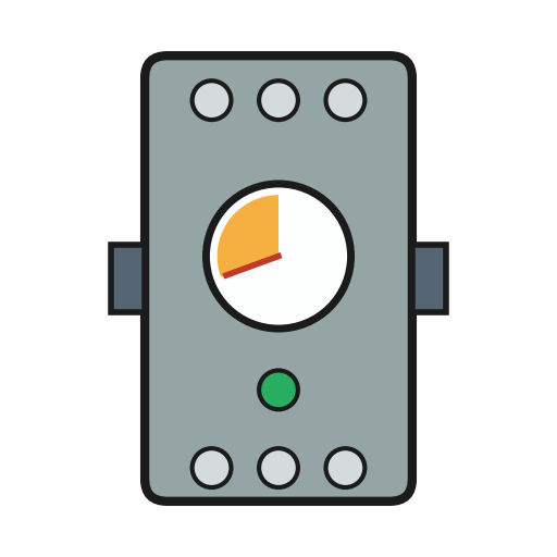 དུས་ཚོད་འགྱངས་པའི་རི་ལེ།1 དུམ་བུ།
ལག་ཆས་དགོས་མཁོ:
 ཐད་རྒྱུན་གློག་ཁུངས།
 མཱལ་ཊི་མི་ཊར།
 ཆུ་ཚོད་བཀག་ཆས།
3
3
The relay it times
The relay it times
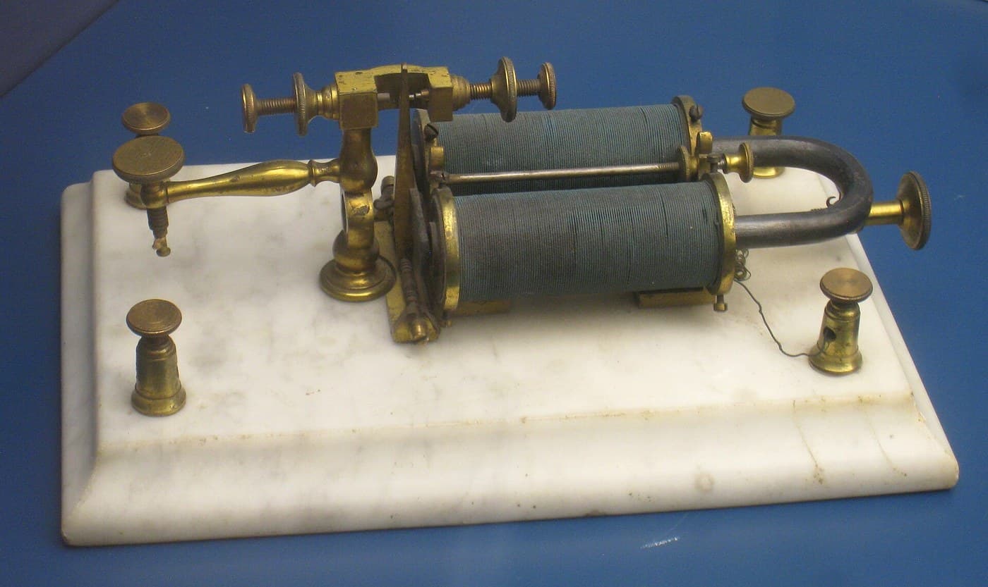
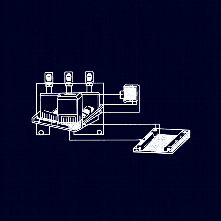
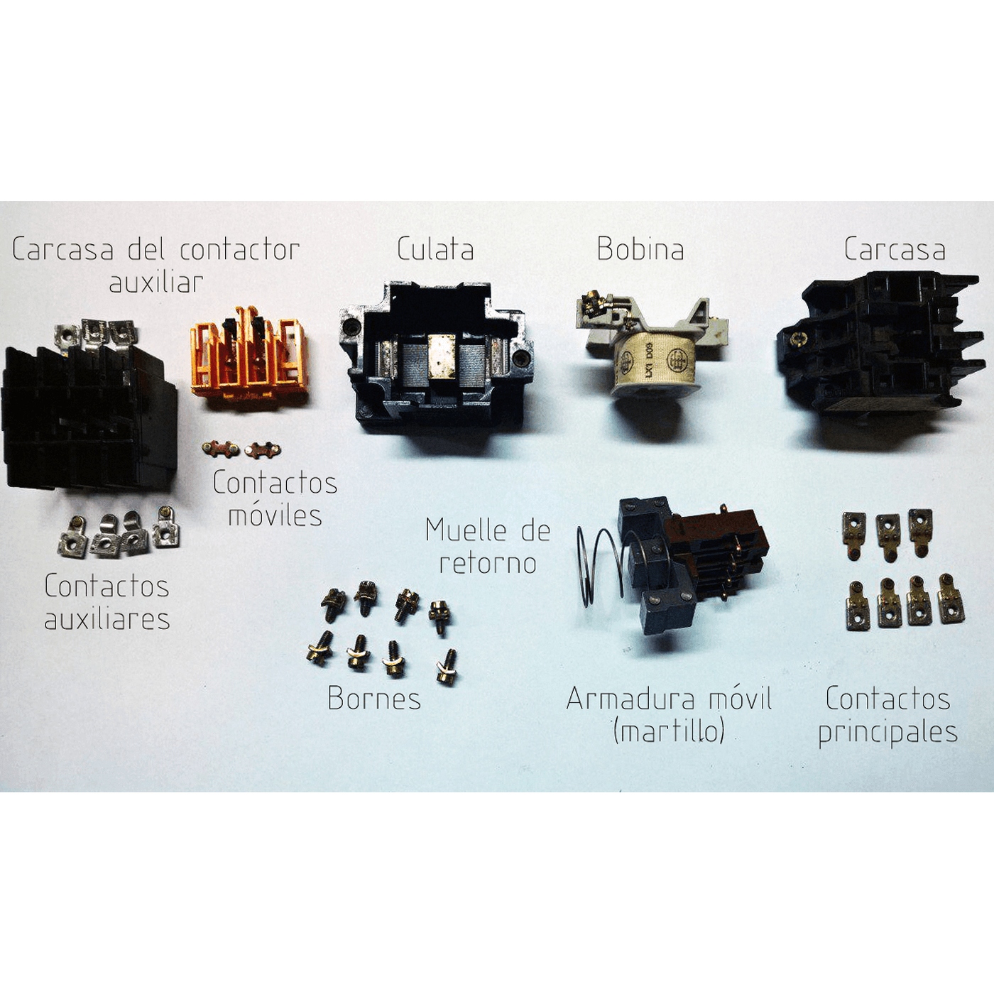
A time-delay relay is a relay with a clock in front of it. The embedded blueprint shows the electromagnetic relay it drives.
4
4
A timer that times wrong
A timer that times wrong
Time-delay relay faults.
Flow
Loading...
5
5
Context and honest limits
Context and honest limits
Pneumatic dashpot timers, thermal timers and motor-driven timers served machine and process control for decades; the 555 timer IC, introduced in 1972, made cheap electronic delays universal, and programmable controllers now provide timers in software.
**Honest limits.** An RC delay drifts with temperature and with the capacitor's age. For accurate long delays use a crystal-timed or counting timer. A relay switching mains loads must be wired and enclosed by someone qualified; the bench build stays at low voltage.
རྫས་རིགས
11- 1 དུམ་བུ།ས་ཆ་འཛིན
- 1 དུམ་བུ།ས་ཆ་འཛིན
- 1 དུམ་བུ།ས་ཆ་འཛིན
- 1 དུམ་བུ།ས་ཆ་འཛིན
- 1 དུམ་བུ།ས་ཆ་འཛིན
- ལས་$5.64
- ལས་$0.51
- ལས་$3.54
- ལས་$9.43
- 1 དུམ་བུ།ས་ཆ་འཛིན
ལག་ཆས་དགོས་མཁོ
3- ས་ཆ་འཛིན
- ས་ཆ་འཛིན
- ས་ཆ་འཛིན
འབྲེལ་ཡོད་བིལུ་པིརིན་ཊི
བིལུ་པིརིན་ཊི་འདི་ཚུ་ཐབས་ལམ་དང་རྫས་རིགས། སྤྱི་ཆོས་བགོ་བཤའ་བྱེད


CC0 སྤྱི་དབང
བིལུ་པིརིན་ཊི་འདི་CC0 འོག་བཀྲམས་ཡོད། ཁྱེད་རང་གིས་ཆོག་མཆན་མ་བཞེས་པར་ཕབ་ལེན་དང་བཟོ་བཅོས། བགོ་བཤའ། དགོས་མཁོ་གང་ལའང་བཀོལ་སྤྱོད་བྱས་ཆོག
བཟོ་མཁན་ལ་རྒྱབ་སྐྱོར་བྱེད་པའི་ཆེད་ཁོང་ཚོའི་བིལུ་པིརིན་ཊི་བརྒྱུད་ཐོན་སྐྱེད་ཉོ། བཟོ་མཁན་གྱིས བཟོ་མཁན་གྱི་ཁེ་ཕོགས ཚོང་པས་གཏན་འཁེལ་བྱས་པ། ཡང་ན་བིལུ་པིརིན་ཊི་འདིའི་པར་གསར་བཟོས་ཏེ་ཁྱེད་རང་གི་བིལུ་པིརིན་ཊི་ནང་མཐུད་སྦྲེལ་བྱས་ཏེ་ཡོང་སྒོ་བགོ་བཤའ་བྱེད།