艺术
美容与健康
工艺
文化与历史
娱乐
环境
食品与饮料
绿色未来
逆向工程
科学
体育
技术
可穿戴设备
已翻译
BLUEPRINT NFT
闪烁 LED — 您的第一个 Arduino 项目
经典的第一个电子项目!使用 Arduino、面包板、一个电阻和单个 LED 构建一个闪烁 LED 电路。非常适合完全初学者 — 无需焊接。
说明
1
1
收集您的组件
收集您的组件
收集下面列出的所有组件。无需焊接——所有东西都插入面包板中。
此步骤所需材料:
 SparkFun Inventor's Kit - V3.21 套件
Arduino Uno R31 个
5mm LED (any color)1 个
 220 ohm Resistor (1/4W)1 个
Breadboard1 个
Jumper Wires (Male-to-Male)2 个
USB-B Cable1 个
所需工具:
Computer with Arduino IDE
2
2
电路示意图
电路示意图
信号从Arduino Pin 13 → 220Ω电阻(R1) → LED(D1) → GND。电阻限制电流以保护LED。
此步骤所需材料:
Arduino Uno R31 个
5mm LED (any color)1 个
220 ohm Resistor (1/4W)1 个3
3
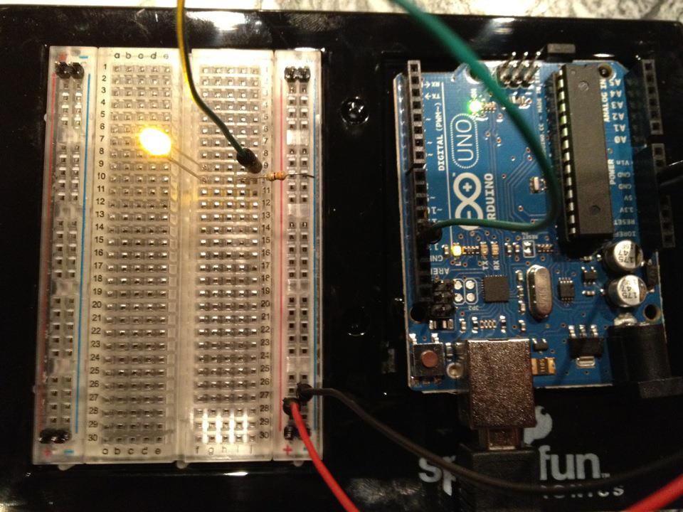
接线
接线
- 将LED插入面包板——长腿(阳极 +)在一行,短腿(阴极 −)在下一行。
- 将220Ω电阻的一条腿插入与LED阴极相同的行。另一条腿在单独的行中。
- 跳线从LED阳极行→Arduino Pin 13。
- 跳线从电阻自由行→Arduino GND。
此步骤所需材料:
5mm LED (any color)1 个
220 ohm Resistor (1/4W)1 个Breadboard1 个
Jumper Wires (Male-to-Male)2 个
4
4
上传 Blink 代码
上传 Blink 代码
通过USB连接Arduino。打开Arduino IDE,选择Tools → Board → Arduino Uno,粘贴代码并点击Upload。
blink.inoarduino
此步骤所需材料:
Arduino Uno R31 个
USB-B Cable1 个
所需工具:
Computer with Arduino IDE
5
5
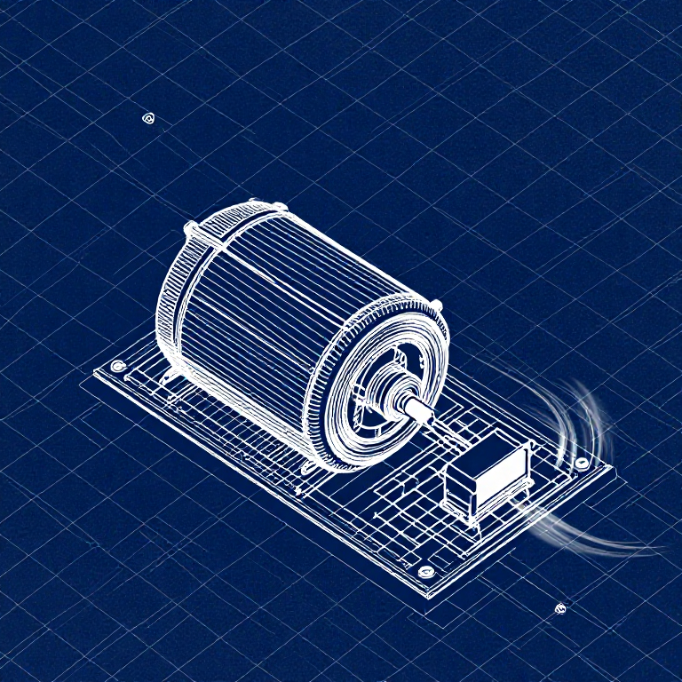
PCB 布局(参考)
PCB 布局(参考)
这显示了作为 PCB 布局的电路。对于本项目不需要——面包板完全可以工作——但显示了如果制造为真实电路板时相同电路的外观。
6
6
测试和实验
测试和实验
LED 闪烁?恭喜! 你刚刚编程了硬件。
故障排除:
下一步实验:
故障排除:
- LED 没有亮起? 翻转 LED — 长腿朝向引脚 13。
- LED 保持开启? 检查代码是否成功上传。
- 没有反应? 验证接线是否与第 2 步中的原理图匹配。
下一步实验:
- 更改
delay()值来控制闪烁速度 - 在引脚 12 上添加第二个 LED
- 替换为 RGB LED(参见 SIK 电路 3)
材料
7- $105.00
估计总额
$105.00Related blueprints
Other builds that share materials, tools, or techniques with this one.

Using a Shift Register — SIK Circuit 14electronics/active
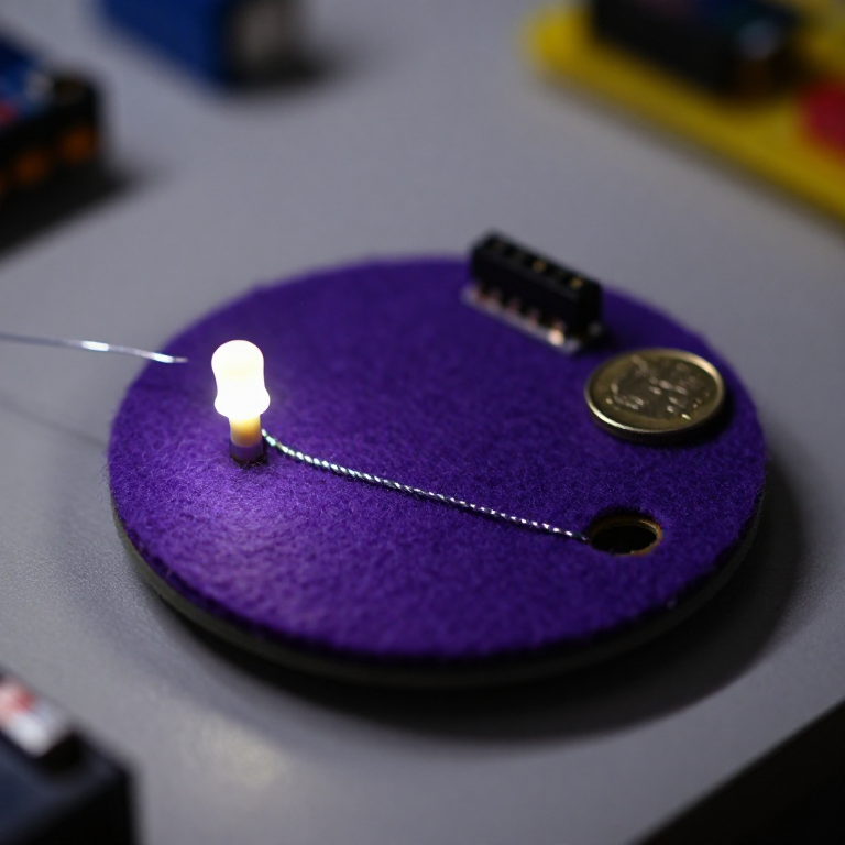
Blinking an LED with LilyPad Arduinoelectronics

Making Charcoal — The First Chemical Processmaterials
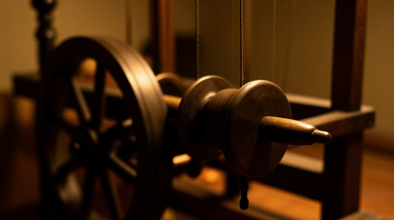
The Spinning Jenny — Multi-Spindle Yarn Productiontextiles
Starting Seeds Indoors — Raising Seedlings for a Head Start
Driving a Motor — SIK Circuit 12electronics/electromech
CC0 公共领域
此蓝图以 CC0 协议发布。你可以自由复制、修改、分发和使用此作品,无需征得许可。
通过购买蓝图中的产品支持创客,他们将获得 创客佣金 (由供应商设定),或创建此蓝图的新版本并将其作为连接包含在你自己的蓝图中以分享收入。