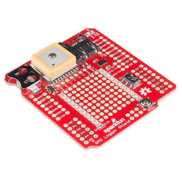


GPS Position Logger
说明
Solder the GPS shield headers
Solder the GPS shield headers
The kit contains the shield, an EM-506 receiver with its interface cable, and R3 headers. Solder the headers to the shield.
此步骤所需材料:
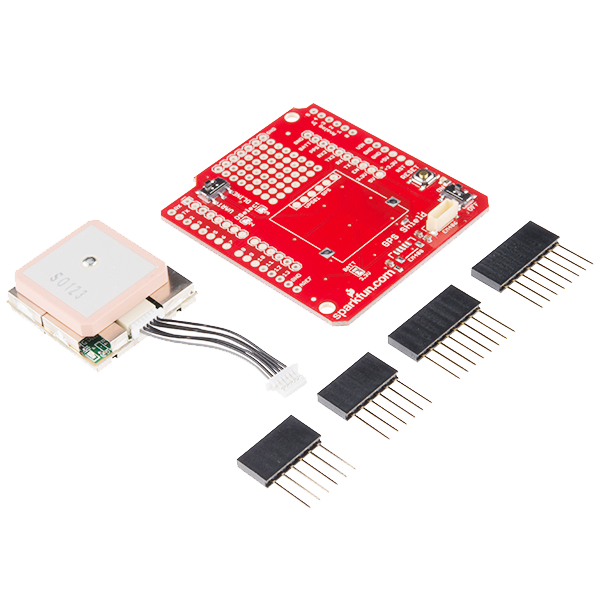 SparkFun GPS Shield Kit1 套件
所需工具:
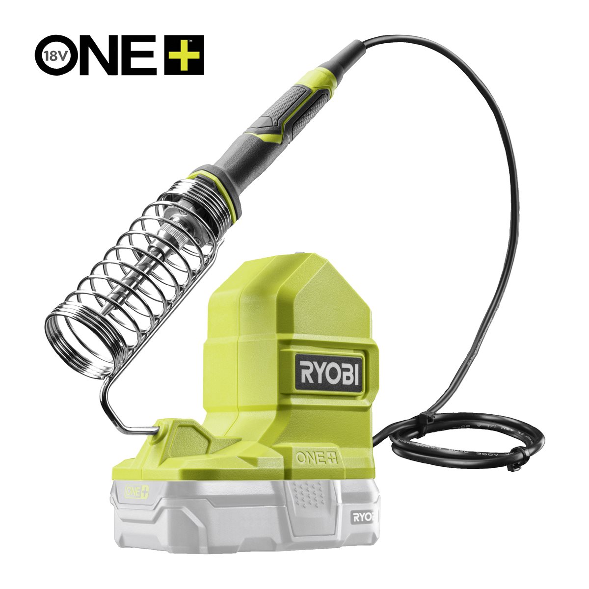 Ryobi ONE+ RSI18-0 Cordless Soldering Iron
Stack both shields and check for pin clashes
Stack both shields and check for pin clashes
Plug the EM-506 into the shield's connector, then stack GPS shield and microSD shield on the Uno.
- GPS shield: receiver on D2/D3 with its switch in the DLINE position.
- microSD shield: SPI on D11/D12/D13, card select on D8.
此步骤所需材料:
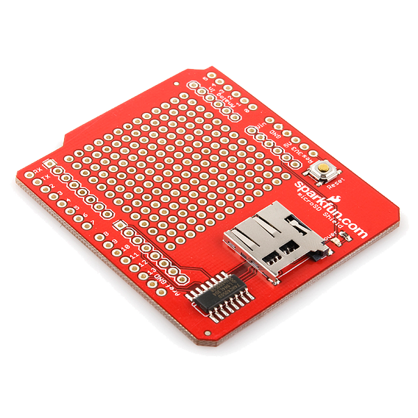 microSD Shield1 个
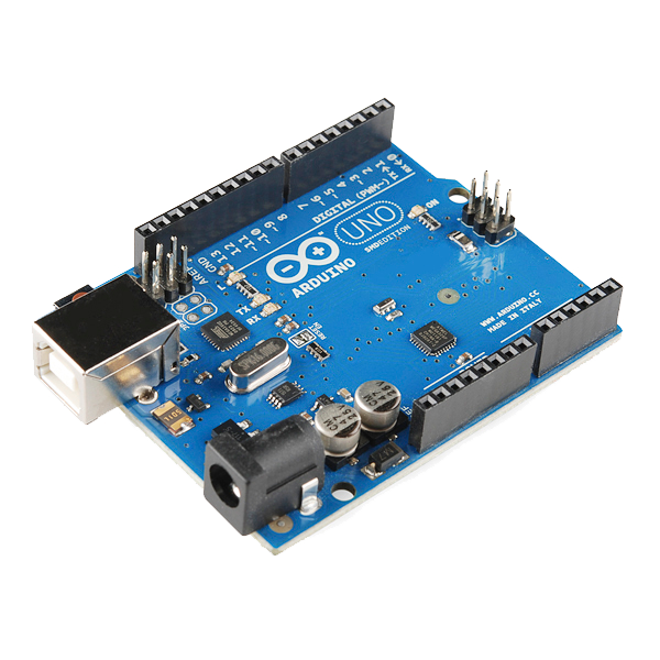 Arduino Uno R3 SMD1 个
Power, and read raw NMEA before parsing anything
Power, and read raw NMEA before parsing anything
USB-B from the computer while testing; 7–12 V on the barrel jack once it runs standalone.
Before writing any parser, print the receiver's output straight through and look at it. You should see comma-separated sentences beginning with $.
Sentences arriving with empty position fields mean the receiver is alive and talking but has no fix yet. That is the normal cold-start state — not a fault.此步骤所需材料:
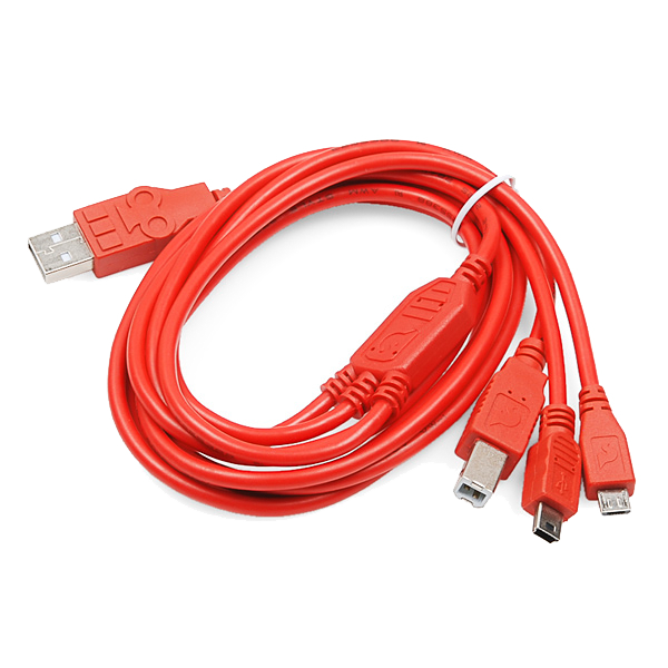 USB-B Cable1 个
Upload the logging sketch
Upload the logging sketch
No GPS library needed — the sketch reads NMEA directly, so nothing is hidden behind an abstraction. SD and SPI ship with the IDE. Format the card FAT32 first.
Take it outside for the first fix
Take it outside for the first fix
Put the unit under open sky, powered, and leave it. Watch for the fix indicator before judging the build.
Testing a GPS receiver indoors and concluding it is broken is the single most common failure in this project. A cold start with no stored almanac legitimately takes minutes.材料
5- SparkFun GPS Shield Kit10% 佣金1 套件$54.28
- microSD Shield10% 佣金1 个$14.14
- Arduino Uno R3 SMD10% 佣金1 个$26.85
- $5.64
- $4.97
所需工具
1- $92.47
CC0 公共领域
此蓝图以 CC0 协议发布。你可以自由复制、修改、分发和使用此作品,无需征得许可。
通过购买蓝图中的产品支持创客,他们将获得 创客佣金 (由供应商设定),或创建此蓝图的新版本并将其作为连接包含在你自己的蓝图中以分享收入。