艺术
美容与健康
工艺
文化与历史
娱乐
环境
食品与饮料
逆向工程
科学
体育
技术
可穿戴设备
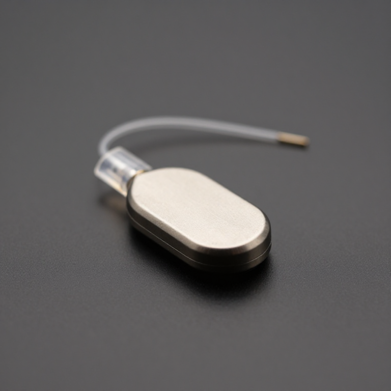


The Implantable Pacemaker
Wilson Greatbatch was building an oscillator to record heart sounds when he reached into a box and fitted the wrong resistor — a megohm where he wanted ten kilohms. The circuit stopped doing what he had asked and started emitting a pulse, then a pause, then a pulse, at about the rate of a heartbeat. He recognised what he was looking at.
That is the whole device. A pacemaker is a relaxation oscillator: something charges slowly, reaches a threshold, dumps its charge as a short sharp pulse, and starts again. The family is the one behind the flip-flop and the multivibrator, and Greatbatch's was a blocking oscillator, a cousin of both.
The engineering that made it implantable was not the circuit. It was the energy budget and the sealing. A device inside a person cannot be recharged and cannot be opened, so its battery is its lifetime, and every microamp of standing current is measured in months of surgery avoided. Greatbatch's later contribution — a lithium-iodine cell — did more for patients than the oscillator did, taking a device that lasted about two years to one that lasted ten.
You will build the oscillator on the bench, add demand inhibition so it stays quiet when a rhythm is already present, and compute the energy budget that decides how long it would live. It drives an indicator and an oscilloscope. It is never connected to a person or an animal, and the sense input comes from a signal generator, not from anybody's chest.
高级
7 hours 30 minutes
说明
1
1
Start from the relaxation oscillator
Start from the relaxation oscillator
Before adding anything clinical, build the oscillator itself and see the family resemblance.
The flip-flop blueprint gives you the cross-coupled pair whose two states each undermine the other. Make one of the coupling paths slow — a resistor charging a capacitor rather than a direct connection — and the circuit stops being bistable and starts being astable: it will not sit still, it flips, waits for the capacitor, flips back. The waiting time is set by the resistor and capacitor together, and that product is the whole of the rate control.
Build it, put it on the scope, and change the resistor. Watch the rate move. Greatbatch's accident was exactly this, arrived at from the other direction: he changed the resistor without meaning to and the rate landed in the range of a human heart.
Once you have it running, note the mark-to-space ratio. A pacemaker needs a very short pulse and a very long gap — under a millisecond of output and most of a second of silence — because the pulse is what costs energy. A symmetrical oscillator would waste hundreds of times more charge than it needs to. Getting that asymmetry is the first real design decision and step 3 is where it pays.
此步骤所需材料:
 晶体管组合1 套
 电阻套件1 套件
 电解电容套件1 套件
 洞洞板/万能板1 个
所需工具:
 焊台
焊台 数字示波器
数字示波器 实验室级数字万用表
2
2
The energy budget is the design
The energy budget is the design
正在加载 Jupyter 笔记本…
所需工具:
 台式电脑
台式电脑3
3
Demand logic on the bench
Demand logic on the bench
A fixed-rate pacer competes with whatever the heart is doing. Demand pacing watches for a natural beat and stays quiet if one arrives in time, pacing only into the silence.
This sketch implements that logic explicitly, with the two timers that define it. The escape interval is how long the circuit waits for a natural beat before pacing. The blanking period after any event — sensed or paced — is a deliberate deafness that stops the circuit from hearing its own output and mistaking it for a heartbeat, which would inhibit it forever.
The sense input is a signal generator or a recorded trace played into the analog pin. Not a person. The output drives an indicator LED and a scope probe through a resistor, at logic level, into a dummy load standing in for a lead. Everything about the program is a bench demonstration of the timing rules, which are the interesting part and are identical in the real device.
demand_pacer_bench.inoarduino
此步骤所需材料:
 Arduino 开发板1 个
 指示灯 LED 套装1 套电阻套件1 套件
所需工具:
 装有 Arduino IDE 的电脑数字示波器
 函数发生器
函数发生器4
4
The timing states, and the failure each guard prevents
The timing states, and the failure each guard prevents
Demand pacing is a small state machine and every state exists to prevent a specific, named failure. This diagram puts the failure next to the guard.
Follow the loop: after any event the circuit is blank, then listening, then either sensing a beat or timing out and pacing. Both outcomes return to blank, which is why the blanking period applies to sensed beats as well as paced ones.
The three failure branches are the ones that killed early devices. Sensing your own output means permanent inhibition and no pacing at all. Sensing external interference means the same. Pacing into the vulnerable window of a beat that is already underway can trigger a dangerous rhythm — which is precisely why demand mode was developed and why a fixed-rate device is not acceptable when a natural rhythm may return.
Read the diagram alongside the sketch in step 3 and check that each guarded transition in the drawing exists as a line of code.
Flow
Loading...
所需工具:
数字示波器函数发生器5
5
Measure the standing current, then stop here
Measure the standing current, then stop here
Do the measurement the notebook says decides everything, because measuring microamps is a skill and most people have never tried.
Put the multimeter in series with the supply on its microamp range and read the current between pulses. On an Arduino you will read milliamps, not microamps — three orders of magnitude worse than the budget in step 2 — because the board is running a crystal, a regulator, a serial chip and an idle loop. That number is the honest result and it is the lesson: the demonstration board is a fine way to learn the timing rules and a hopeless way to build anything that must live on a cell for years.
Then do it properly on the discrete oscillator from step 1. Strip it to the transistor pair, the timing resistor and the capacitor, run it from a coin cell, and measure again. Trade the timing resistor upward and watch the standing current fall and the rate slow together — they are the same resistor, which is the fundamental tension in the whole design and the reason the real devices moved to a different topology entirely.
Where this stops, and it stops here completely. You have built a relaxation oscillator, implemented demand timing, and measured an energy budget. All three are genuine and transfer to any long-lived low-power device — a remote sensor, a tracker, a datalogger meant to run for years untouched.
What you have not built, and must not attempt, is a medical device. An implantable pacemaker is hermetically sealed against body fluid for a decade, biocompatible in every exposed material, protected against defibrillation and electrosurgery and magnetic fields, fitted with a lead whose fixation and impedance are verified at implant, programmable and interrogable without opening the patient, manufactured under regulation with full traceability, and implanted and followed by a clinical team. A failure is not a bug. Do not connect this circuit to any living thing, do not use it to observe anybody's rhythm, and if you or someone near you has a heart rhythm question, that is a question for a clinician and not for a bench.
此步骤所需材料:
 CR2032 纽扣电池2 个电阻套件1 套件
所需工具:
实验室级数字万用表数字示波器焊台材料
7- 1 套占位符
- 1 套件占位符
- 1 个占位符
- 1 个占位符
- 1 套占位符
- 2 个占位符
相关蓝图
这些蓝图共享知识——技术、材料或原理

CC0 公共领域
此蓝图以 CC0 协议发布。你可以自由复制、修改、分发和使用此作品,无需征得许可。
通过购买蓝图中的产品支持创客,他们将获得 创客佣金 (由供应商设定),或创建此蓝图的新版本并将其作为连接包含在你自己的蓝图中以分享收入。