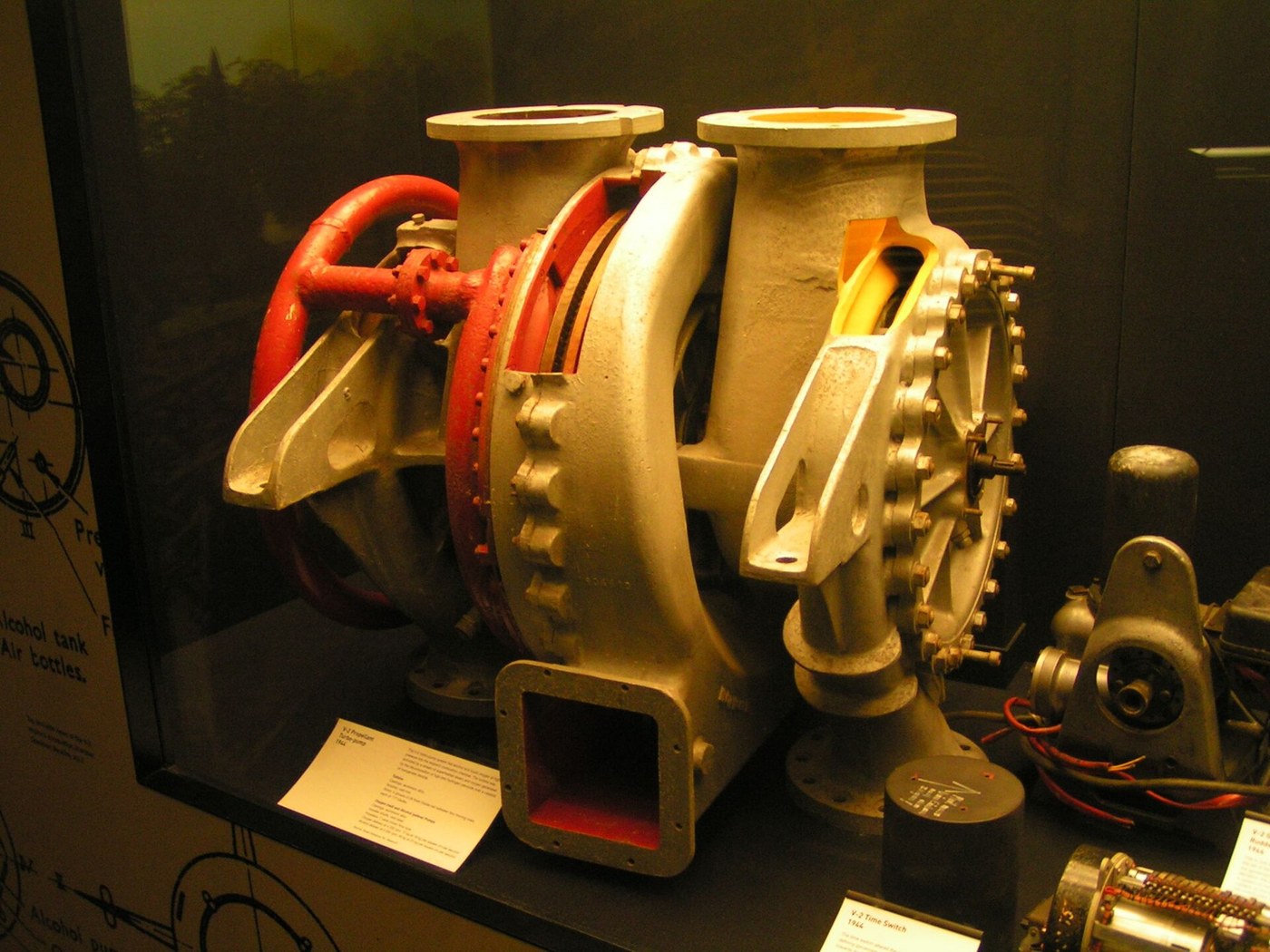


The Rocket Turbopump
说明
Weigh a pressure-fed tank and see why it loses
Weigh a pressure-fed tank and see why it loses
Quantify the alternative before building the complicated thing.
- For a chosen tank volume, compute the wall thickness needed to hold 5 bar with a sensible safety factor, and its mass.
- Repeat for 50 bar, and again for 300 bar.
- Plot tank mass against pressure.
- Compare each against the propellant mass the tank would hold.
Tank mass rises roughly in proportion to pressure, and by a few hundred bar the tank weighs more than what is inside it. Since the rocket equation cares about the ratio of full to empty mass, that is fatal — you have added dry mass in exchange for nothing.
Pressure-fed systems are still the right answer for small upper stages, attitude thrusters and anything valuing simplicity over performance, because there is nothing to spin up and nothing to fail. The trade turns on chamber pressure: below roughly 20 bar pressure-fed wins on mass and simplicity, above it the pump wins decisively.此步骤所需材料:
 坐标纸1 pad
所需工具:
 6 英寸数显卡尺
 数字天平
数字天平 压力表
压力表Build a centrifugal pump and measure its head curve
Build a centrifugal pump and measure its head curve
Same machine as the turbojet compressor, running on liquid instead of gas.
- Machine or adapt a centrifugal impeller in a volute housing, driven by a variable-speed motor.
- Pump water and measure delivered pressure against flow rate at a fixed speed, throttling the outlet in steps.
- Plot pressure head against flow.
- Repeat at several speeds and compare.
Head is highest at zero flow and falls as flow increases, and head rises with the SQUARE of rotational speed while flow rises only linearly. That square law is why turbopumps run at tens of thousands of rpm — the pressure you need is bought far more cheaply with speed than with size.
Reverse-engineering note: the impeller of a rocket turbopump is a single machined piece, usually milled from a solid forging rather than cast, because at these speeds a casting defect is a burst. The blades are backward-curved for the same reason as in the turbojet: it gives a stable, gently falling head curve rather than one that can wander.此步骤所需材料:
 涡轮增压器压气机叶轮1 个
 铝圆棒1 个
 滚珠轴承2 个坐标纸1 pad
所需工具:
 金属车床
金属车床 4 英寸铣床虎钳
 百分表6 英寸数显卡尺
 数字转速表压力表
 扭力扳手
扭力扳手 透明安全眼镜
 护耳器(耳罩,SNR 30 dB)
Find cavitation, and then defeat it with an inducer
Find cavitation, and then defeat it with an inducer
The failure that destroys pumps is not overload — it is the liquid boiling at the inlet.
- Run the pump and progressively restrict the INLET while listening and watching delivered pressure.
- Note the point where the sound turns to a gravelly rattle and head collapses.
- Stop immediately and inspect the impeller leading edges.
- Now fit an inducer — a small axial screw upstream of the main impeller — and repeat.
Restricting the inlet drops local pressure below the liquid’s vapour pressure, so it boils at the impeller eye; those bubbles collapse violently a moment later in the higher-pressure region and hammer the metal. Cavitation sounds like pumping gravel, destroys head, and pits impellers into lace.
The inducer solves it by raising pressure gently before the main impeller ever sees the flow. It is a low-head pump whose only job is to keep the real pump out of trouble, and every rocket turbopump has one.
This is also why tanks are pressurised at all in a pumped system — that few bar of ullage pressure exists purely to keep the pump inlet above vapour pressure. It is not helping deliver propellant; it is preventing cavitation. Cryogenic propellants make it harder, because they are stored at their boiling point by definition.此步骤所需材料:
铝圆棒1 个坐标纸1 pad所需工具:
金属车床4 英寸铣床虎钳压力表数字转速表 可拍慢动作视频的智能手机6 英寸数显卡尺透明安全眼镜护耳器(耳罩,SNR 30 dB)
Drive it with a turbine, and choose a cycle
Drive it with a turbine, and choose a cycle
Something must spin the pump, and where its energy comes from defines the whole engine.
- Sketch three arrangements. Gas generator: a small side combustor burns a little propellant, drives the turbine, and dumps its exhaust overboard. Staged combustion: a preburner runs very fuel-rich, drives the turbine, and its exhaust — still full of unburned fuel — goes into the main chamber. Expander: fuel warmed in the regenerative cooling jacket is used to drive the turbine before being injected.
- For each, trace where the turbine’s working fluid ends up.
- Mark which arrangements waste propellant.
The gas generator throws away a small percentage of propellant unburned — visible as the dark smoky exhaust alongside the main plume on older engines. Staged combustion wastes none, and pays with far higher turbine pressures and much harder engineering.
The expander cycle is the elegant one and ties straight back to the previous blueprint: the heat picked up while cooling the chamber is used to drive the pump, and then still gets burned. Its limit is that only so much heat is available, which caps engine size — which is why expander engines are upper stages.
Each cycle is a different answer to one question: what drives the turbine, and does its exhaust get wasted? That single choice sets the engine's efficiency, its complexity and its cost more than any other decision in the design.此步骤所需材料:
坐标纸1 pad所需工具:
6 英寸数显卡尺数字转速表 带读数的热电偶
Seal the shaft between things that must never meet
Seal the shaft between things that must never meet
One shaft passes from the oxidiser pump to the fuel pump, and a leak between them is not a maintenance issue.
- Examine the problem: liquid oxygen on one end, kerosene or hydrogen on the other, one rotating shaft between them.
- Design a seal package — two mechanical face seals with a vented cavity between them.
- Pipe an inert purge gas into that cavity at a pressure above both sides.
- Test with air and dyed water, checking that neither fluid reaches the other even when one seal is deliberately degraded.
The intermediate purged cavity is the whole design: any leak past either seal goes into the purge and out to vent, never across. A single seal, however good, has one failure between two propellants that ignite on contact.
Recognise the pattern from earlier in this catalogue — this is the same reasoning as the double seal on the SF6 breaker shaft and the vented interspace in a hydraulic gland. Where a single barrier failing is catastrophic, use two and monitor the space between, so the first failure is detectable rather than fatal.
The 1969 N1 launches are the standard cautionary tale here: turbopump failures in a first stage with thirty engines, where debris from one destroyed its neighbours. Rocket turbopumps operate closer to their material limits than almost any other production machinery, and there is very little margin between working and disassembling.此步骤所需材料:
 机械端面密封套装2 套
 O 形圈组合套件1 套件
 食用色素(流动显示用染料)1 瓶
所需工具:
金属车床4 英寸铣床虎钳百分表6 英寸数显卡尺压力表 30 加仑空气压缩机扭力扳手透明安全眼镜
材料
7- 1 pad占位符
- 1 个占位符
- 1 个占位符
- 占位符
- 2 套占位符
- 1 套件占位符
- 占位符
相关蓝图
这些蓝图共享知识——技术、材料或原理

CC0 公共领域
此蓝图以 CC0 协议发布。你可以自由复制、修改、分发和使用此作品,无需征得许可。
通过购买蓝图中的产品支持创客,他们将获得 创客佣金 (由供应商设定),或创建此蓝图的新版本并将其作为连接包含在你自己的蓝图中以分享收入。