Driving an RGB LED — SIK Circuit 3
说明
Parts & Introduction
Parts & Introduction
An RGB LED contains three tiny LEDs (red, green, blue) in one package. By mixing different brightness levels of each color, you can create any color in the rainbow. This experiment introduces analogWrite() for PWM output.
Parts Needed
- 1x Arduino Uno + USB cable
- 1x Breadboard
- 1x RGB LED (Common Cathode)
- 3x 330Ω Resistors
- 5x Jumper Wires
RGB LED Pin Order (flat edge facing you): Red, Ground (longest pin), Green, Blue.
此步骤所需材料:
 SparkFun Inventors Kit - V3.21 套件
 RGB LED (Common Cathode)1 个
 330 Ohm Resistor3 个
 Jumper Wires5 个
所需工具:
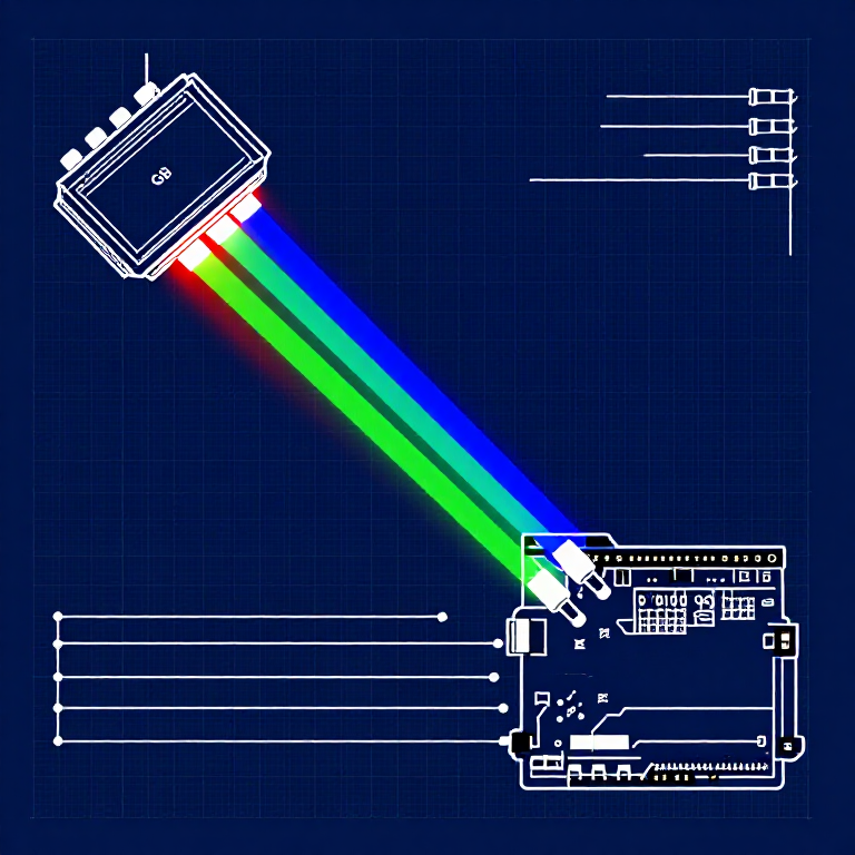
Hardware Hookup
Hardware Hookup
Wiring Instructions
- Place the RGB LED in the breadboard. Identify pins from the flattened edge: Red, GND (longest), Green, Blue.
- Connect the GND pin (longest, second from left) to the GND rail.
- Connect the Red pin through a 330Ω resistor to Arduino Pin 9.
- Connect the Green pin through a 330Ω resistor to Arduino Pin 10.
- Connect the Blue pin through a 330Ω resistor to Arduino Pin 11.
Pins 9, 10, and 11 are all PWM-capable (marked with ~ on the board).
此步骤所需材料:
RGB LED (Common Cathode)1 个330 Ohm Resistor3 个Jumper Wires5 个Arduino Code
Arduino Code
Open the Arduino IDE and upload the following sketch to your Arduino board.
此步骤所需材料:
所需工具:
Test & Experiment
Test & Experiment
What You Should See
The LED cycles through 8 solid colors (off, red, green, blue, yellow, cyan, purple, white) for 1 second each, then smoothly fades through the entire color spectrum.
Troubleshooting
- Incorrect colors: With four pins close together, it's easy to misplace one. Double-check each connection.
- Red too bright: The red diode is often brighter. Try a higher-value resistor on the red pin, or reduce in code:
analogWrite(RED_PIN, redIntensity/3).
Experiments to Try
- Add a potentiometer to control which color is displayed.
- Create your own color sequences — try a "sunrise" effect (dark red → orange → yellow → white).
材料
6- $105.00
CC0 公共领域
此蓝图以 CC0 协议发布。你可以自由复制、修改、分发和使用此作品,无需征得许可。
通过购买蓝图中的产品支持创客,他们将获得 创客佣金 (由供应商设定),或创建此蓝图的新版本并将其作为连接包含在你自己的蓝图中以分享收入。