艺术
美容与健康
工艺
文化与历史
娱乐
环境
食品与饮料
逆向工程
科学
体育
技术
可穿戴设备
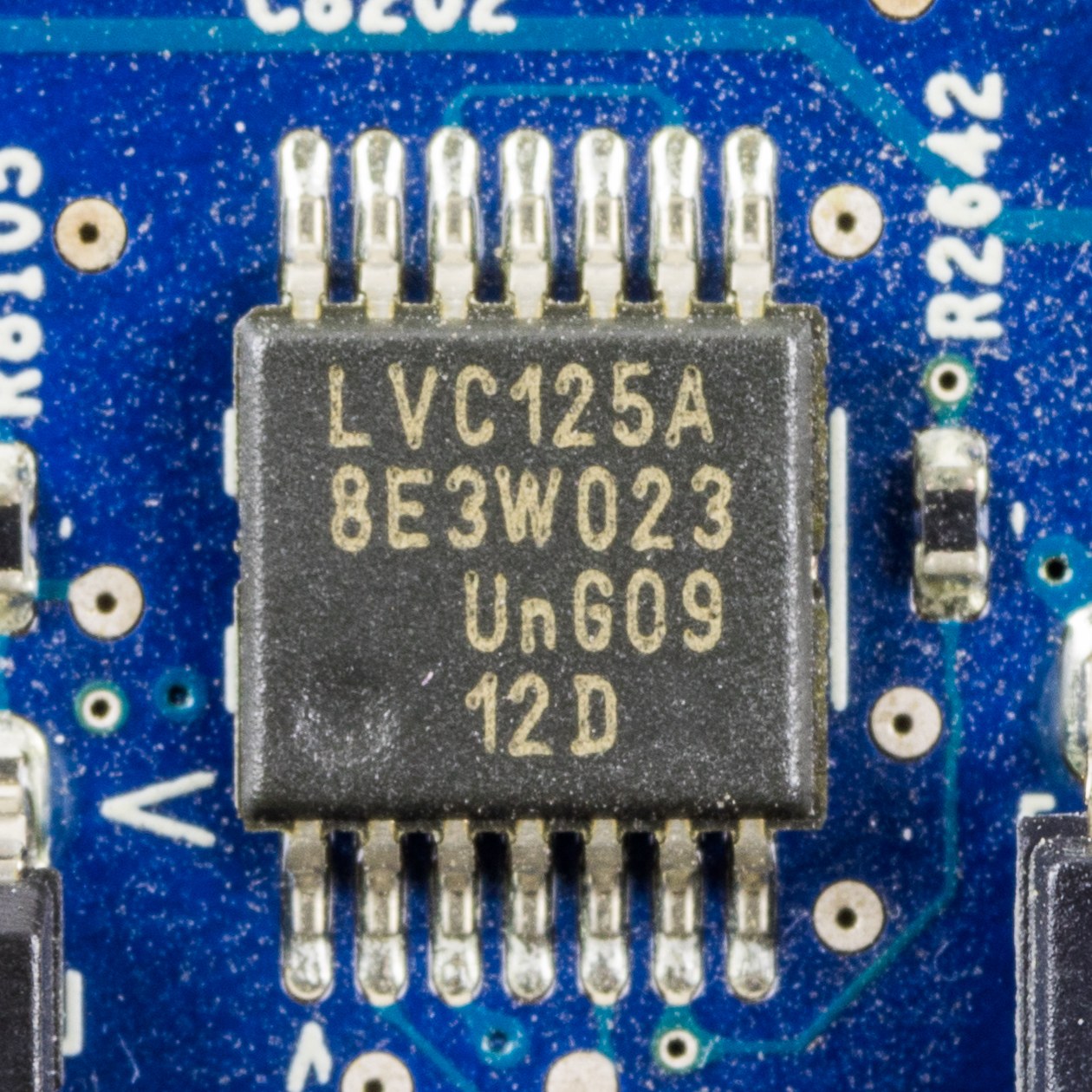


Surface Mount and the Gull Wing
This is the sibling of `lead-frame-dip-package`. Same job — fan a die's connections out to something a board can use, seal it, and conduct its heat away — and one change that follows from a single decision: do not put the leads through the board.
A DIP's leads go through drilled holes and are soldered on the far side. That means every pin needs a hole, holes cost money and board area, a hole occupies BOTH sides of the board so nothing can sit opposite, and the lead has to be long enough to reach through.
Surface mount stops at the surface. The lead is bent out and down into a shallow foot that sits ON a pad, and solder paste printed onto that pad is melted to make the joint. No hole, no far side, no long lead.
Every advantage falls out of that. Both sides of the board become usable, which halves the area at a stroke. Leads can go on all four edges instead of two, so pin count is no longer proportional to package length. The leads are one to two millimetres instead of six to fifteen, which cuts inductance by the same factor and is what let clock rates rise. And assembly becomes a machine placing parts on paste rather than a machine pushing pins through holes, which is faster and works for parts far too small to have pins at all.
The classic lead shape is the GULL WING: out from the body, down, then flat. It is named for what it looks like end-on and it is a compromise. The horizontal foot gives a solderable, INSPECTABLE joint you can see and probe. The bend gives compliance, which the joint badly needs, because unlike a through-hole lead the solder joint is now the only thing holding the part on AND the only thing absorbing the expansion mismatch between package and board.
That last point is the whole reliability story of surface mount, and it is why this blueprint spends its measurement effort on thermal cycling rather than on soldering.
中级
6 hours
说明
1
1
Reflow solder a board, and cycle it until the joints fail
Reflow solder a board, and cycle it until the joints fail
Surface mount is assembled by printing solder paste, placing parts on it, and heating the whole board through a profile. Reproduce that, then attack the result.
PRINT THE PASTE. A stencil is a thin steel or polyimide sheet with apertures over each pad. You can cut one from 100 micrometre polyimide with a craft knife for a coarse footprint, or buy one, or simply dispense paste from a syringe onto each pad. Aim for a consistent volume — the joint's strength and its stand-off both depend on it, and inconsistent paste is the commonest cause of a bad hand-reflowed board.
PLACE THE PARTS with tweezers. Precision is less critical than people expect, because of a genuinely useful effect: molten solder's surface tension pulls a slightly misplaced part into alignment with its pads. A part placed within a third of a pad width will usually self-centre. That self-alignment is one of the quiet reasons surface mount scaled to machine assembly at all.
REFLOW IT. A hotplate works for a small board, or a modified toaster oven, or a proper reflow plate. The profile matters and has four phases: preheat to about 150 degrees to bring everything up evenly, soak at 150 to 180 for a minute or two to activate the flux and let the board equalise, ramp to peak — around 240 for lead-free, 215 for leaded — for 30 to 60 seconds above the melting point, then cool.
WATCH IT REFLOW. There is a distinct moment where the paste goes from dull grey to bright and liquid, and parts visibly twitch into alignment. That moment is the process; everything before it is preparation and everything after is cooling.
INSPECT THE FILLETS. A good gull-wing joint has a concave fillet that wets up the side of the lead. Too little paste gives a thin joint with no fillet; too much gives a bulging joint and risks bridging to the neighbour. Photograph them under the microscope — and note that you CAN photograph them, which you could not do with a J-lead or a BGA.
NOW THE MEASUREMENT THAT MATTERS. Wire the board so you can measure continuity through a chain of joints — a daisy chain through every pin of a part, which is exactly what test coupons do in industry.
Thermal cycle it. Between a domestic freezer and an oven at 100 degrees, twenty minutes each way, and measure the chain resistance every ten cycles. Or use a hotplate and a fan for faster, smaller cycles.
The resistance rises before anything opens. A solder joint under cyclic strain accumulates fatigue cracks, and a partially cracked joint is a higher-resistance joint long before it is an open one. Plot resistance against cycle count and you get a curve that is flat, then rises, then goes open — the same shape as flash endurance and the same shape as die-attach delamination, from a completely different mechanism.
That is why through-hole survives in high-vibration and high-cycling applications: a through-hole lead is mechanically anchored by the board itself, and its solder joint is not the only thing holding it on.
此步骤所需材料:
 锡膏(无铅)1 个
 空白印制电路板(覆铜板)4 个
 SOIC 测试元件10 个
 聚酰亚胺薄膜1 个
 99% 异丙醇500 millilitre
 Hook-Up Wire5 metre
所需工具:
 加热磁力搅拌器
 数码显微镜
数码显微镜 精密镊子套装
 实验室级数字万用表
 红外测温仪
红外测温仪 手工刀
手工刀2
2
Area, inductance and fatigue — the three-way trade
Area, inductance and fatigue — the three-way trade
正在加载 Jupyter 笔记本…
所需工具:
 台式电脑
台式电脑材料
6- 1 个占位符
- 4 个占位符
- 10 个占位符
- 1 个占位符
- 500 millilitre占位符
- 5 metre$16.70
估计总额
制作者买了什么。未标价的材料,在你购买的地方获取。
相关蓝图
这些蓝图共享知识——技术、材料或原理

CC0 公共领域
此蓝图以 CC0 协议发布。你可以自由复制、修改、分发和使用此作品,无需征得许可。
通过购买蓝图中的产品支持创客,他们将获得 创客佣金 (由供应商设定),或创建此蓝图的新版本并将其作为连接包含在你自己的蓝图中以分享收入。