Zusammenarbeit
KUNST
SCHÖNHEIT & WELLNESS
HANDWERK
KULTUR & GESCHICHTE
UNTERHALTUNG
UMFELD
ESSEN & GETRÄNKE
REVERSE ENGINEERING
WISSENSCHAFTEN
SPORT
TECHNOLOGIE
WEARABLES
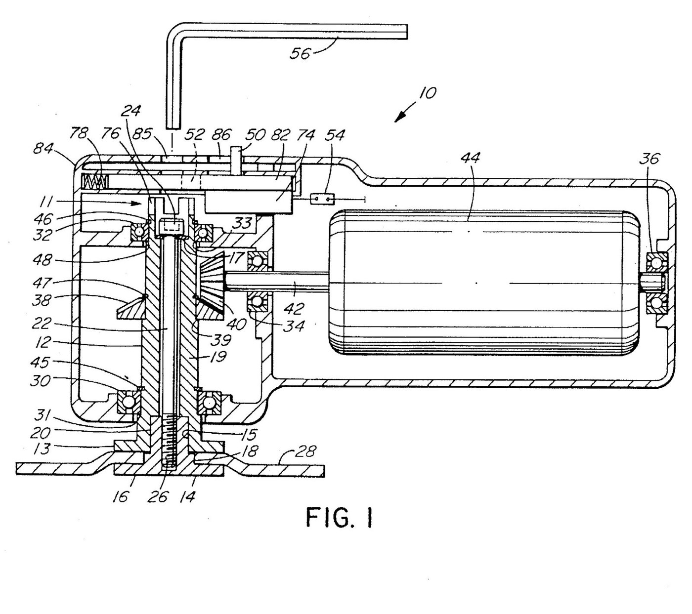


Angle Grinder: Reversible, with a Hollow Arbour and a Top Arbour Lock (Turley, US 5,718,621)
An angle grinder spins a disc at right angles to its motor: a bevel gear on the motor shaft turns a bevel gear on an upright arbour. E. M. Turley (US 5,718,621, 1998) makes the arbour hollow. A bolt runs down through it into a hexagonal coupling piece that drives the disc and clamps it against the arbour's flange, so the motor can run either way without loosening the disc.
To change the disc, a sliding lock piece on top locks the arbour, opens a hole over the bolt head and switches the motor off in one move.
Source: E. M. Turley, "Reversible Angle Grinder with Top Arbour Lock", US Patent 5,718,621 (filed 1996, granted 1998). Picture: its Fig. 1.
Erfahren
Unknown
Anweisungen
1
1
Read Turley
Read Turley
"The angle grinder according to the preferred embodiment of the invention includes a reversible motor driving a hollow arbour via a right angle bevel gear arrangement. The arbour has a right angle flange at its bottom. The flange abuts against one side of the disk tool."
2
2
Turn the hollow arbour
Turn the hollow arbour
Turn an arbour hollow all through, with three outside shoulders (lower, middle and upper) for the two bearings and the bevel gear, and grooves above each for a snap ring. At the bottom, enlarge the bore into a hexagonal recess ending in a right-angle flange. At the top, enlarge the bore so the bolt head sits below the rim, and cut four equally spaced square notches (crenellations) in the rim. Sizes and metal are not given.
Materialien für diesen Schritt:
 Unbekanntes Metall1 arbour
Benötigte Werkzeuge:
 Metalldrehmaschine
 Fräsmaschine
 Feilen (Handfeile)
 Unbekannte Maße
3
3
Make the coupling piece and bolt
Make the coupling piece and bolt
Make a coupling piece: a hexagonal upper part that fits the arbour's recess, a round pilot that fits the standard centre hole of commercial grinding discs, and a right-angle flange at its base. Bore and tap it from the top, closed at the bottom. Make a retaining bolt long enough to run from the arbour's top down into the coupling piece, threaded at its lower end (Fig. 1 draws a socket in its head).
Materialien für diesen Schritt:
Unbekanntes Metall1 coupling pieceUnbekanntes Metall1 retaining boltBenötigte Werkzeuge:
MetalldrehmaschineFräsmaschine GewindeschneidsatzUnbekannte Maße
4
4
Cut the bevel gears
Cut the bevel gears
Cut two bevel gears with teeth at forty-five degrees (equal gears for a right-angle drive): one fixed on the arbour against its middle shoulder, one on the front end of the motor shaft. Tooth count and metal are not given.
Materialien für diesen Schritt:
Unbekanntes Metall2 bevel gearsBenötigte Werkzeuge:
Fräsmaschine KegelradfräserUnbekannte Maße
5
5
Assemble the drive
Assemble the drive
Mount a reversible electric motor in the housing, its shaft running back in a rear bearing and forward in a front bearing, the bevel gear on its front end. Set the arbour upright in two bearings at its lower and upper shoulders, the bevel gears meshing, with snap rings above the bearings and the gear. Drop the bolt down the arbour on a lock washer, fit the coupling piece from below and screw it on. Motor rating, housing material and how the bearings are held are not given.
Materialien für diesen Schritt:
 Elektromotor1 reversible
 Kugellager4 Stück
 Unbekanntes Material1 housing
Benötigte Werkzeuge:
 Innensechskant-Schlüsselsatz
 Unbekanntes UmformverfahrenUnbekannte Maße
6
6
Fit the arbour lock
Fit the arbour lock
Make a rectangular lock piece that slides in the housing top across the arbour head, with a lever up through a slot in the housing, a tool hole, and a square tang underneath that drops into a rim notch. A spring on its front face holds it back in the running position. Fix a two-contact power switch to its rear so the motor circuit is broken when the piece is slid into the locking position. Cut a hole in the housing top over the bolt head and a slot for the lever.
Materialien für diesen Schritt:
Unbekanntes Metall1 lock piece Feder1 Stück
 Ein-/Ausschalter1 Stück
Benötigte Werkzeuge:
Fräsmaschine Standbohrmaschine
 BohrersatzFeilen (Handfeile)
7
7
Change a disc
Change a disc
Push the lever forward: the tang locks the arbour, the switch cuts the motor and the tool hole sits over the bolt head. Unscrew the bolt from above with the key and pull the coupling piece; put the new disc on its pilot and screw it back up tight, so the disc is clamped between the arbour flange and the coupling flange. Let the lever spring back to run. Turley: a loose bolt cannot drop the disc, which rattles to warn you to tighten it.
Benötigte Werkzeuge:
Innensechskant-SchlüsselsatzMaterialien
6- 1 lock piecePlatzhalter
- 1 reversiblePlatzhalter
- Platzhalter
- 1 housingPlatzhalter
- 1 StückPlatzhalter
- 1 StückPlatzhalter
Benötigte Werkzeuge
10- Platzhalter
- Platzhalter
- Platzhalter
- Platzhalter
- Platzhalter
- Platzhalter
- Platzhalter
- Platzhalter
- Platzhalter
- Platzhalter
Dieser Bauplan stellt her

CC0 Gemeinfrei
Dieser Blueprint ist unter CC0 veröffentlicht. Sie dürfen dieses Werk für jeden Zweck frei kopieren, ändern, verbreiten und verwenden, ohne um Erlaubnis zu fragen.
Unterstützen Sie den Maker, indem Sie Produkte über seinen Blueprint kaufen, wo er eine Maker-Provision von Anbietern festgelegt, verdient. Oder erstellen Sie eine neue Iteration dieses Blueprints und verbinden Sie ihn in Ihrem eigenen Blueprint, um Einnahmen zu teilen.