
KUNST
SCHÖNHEIT & WELLNESS
HANDWERK
KULTUR & GESCHICHTE
UNTERHALTUNG
UMFELD
ESSEN & GETRÄNKE
REVERSE ENGINEERING
WISSENSCHAFTEN
SPORT
TECHNOLOGIE
WEARABLES
Bench Drill Press with Raising Head and Tilt Table: Brazell, 1997
Emma

Erstellt von

Emma

12. Oktober 2026SE
24
0
0
0
0

Bench Drill Press with Raising Head and Tilt Table: Brazell, 1997

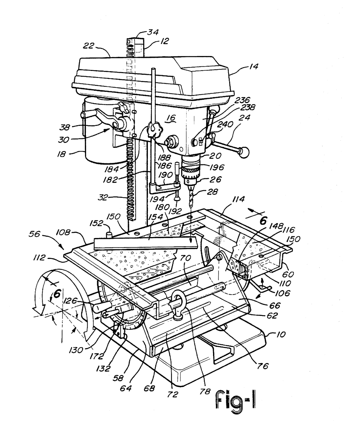
Most home drill presses kept the head fixed and moved the work relative to it. Kenneth M. Brazell and colleagues at Ryobi patented the reverse in 1997, US 5,634,748. A cast iron base sits on the work bench, a column rises from it, and the whole drill head, with its motor and quill, is raised and lowered along the column by a crank and a rack, or swung round it. A tilt table made of stamped and folded sheet steel locks to the base with one cam and eyebolt, slides two ways and turns on the base, and tilts to drill holes at an angle. Its replaceable ¾" particle board panel supports the stock underneath, preventing tear-out.
Erfahren
Factory process

Anweisungen

1

Base and column

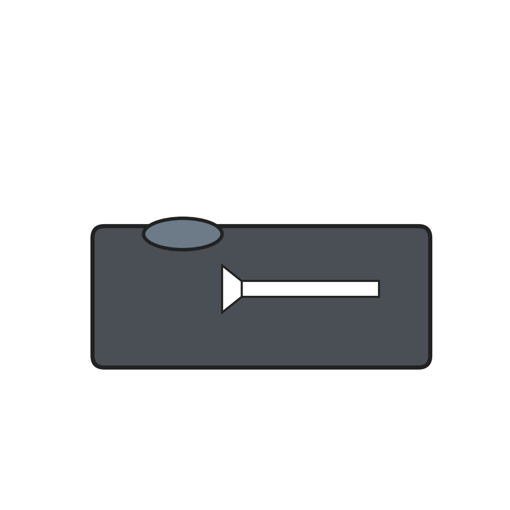
Cast the base with a collar near its rear end to take the column, a transverse slot with a funnel-shaped entrance at the front for the table's lock, and two keyhole slots whose round ends take standard ½ inch carriage bolts for clamping vices. Fix the column in the collar.

Materialien für diesen Schritt:

Gusseisenfuß für SäulenbohrmaschineGusseisenfuß für Säulenbohrmaschine1 Stück
BohrmaschinensäuleBohrmaschinensäule1 Stück

Benötigte Werkzeuge:
GießpfanneGießpfanne
RollgabelschlüsselRollgabelschlüssel
2

Rack on a turning cap

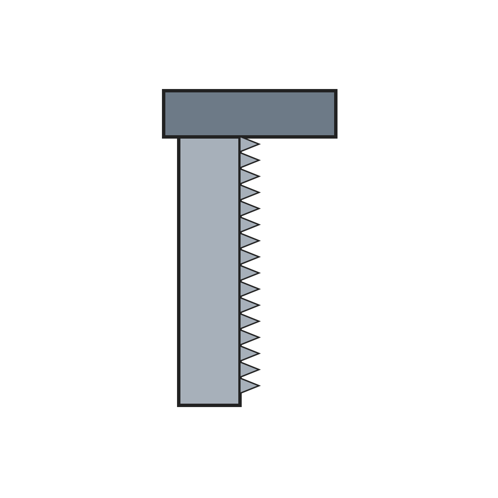
Screw the rack to a cap that fits over the top of the column. Two opposite pins in the column ride in an annular slot in the cap, so the cap turns but cannot lift off. The rack runs down most of the column's length.

Materialien für diesen Schritt:

Säulenzahnstange mit DrehkappeSäulenzahnstange mit Drehkappe1 Stück

Benötigte Werkzeuge:
Schraubendreher-SatzSchraubendreher-Satz
3

Head frame

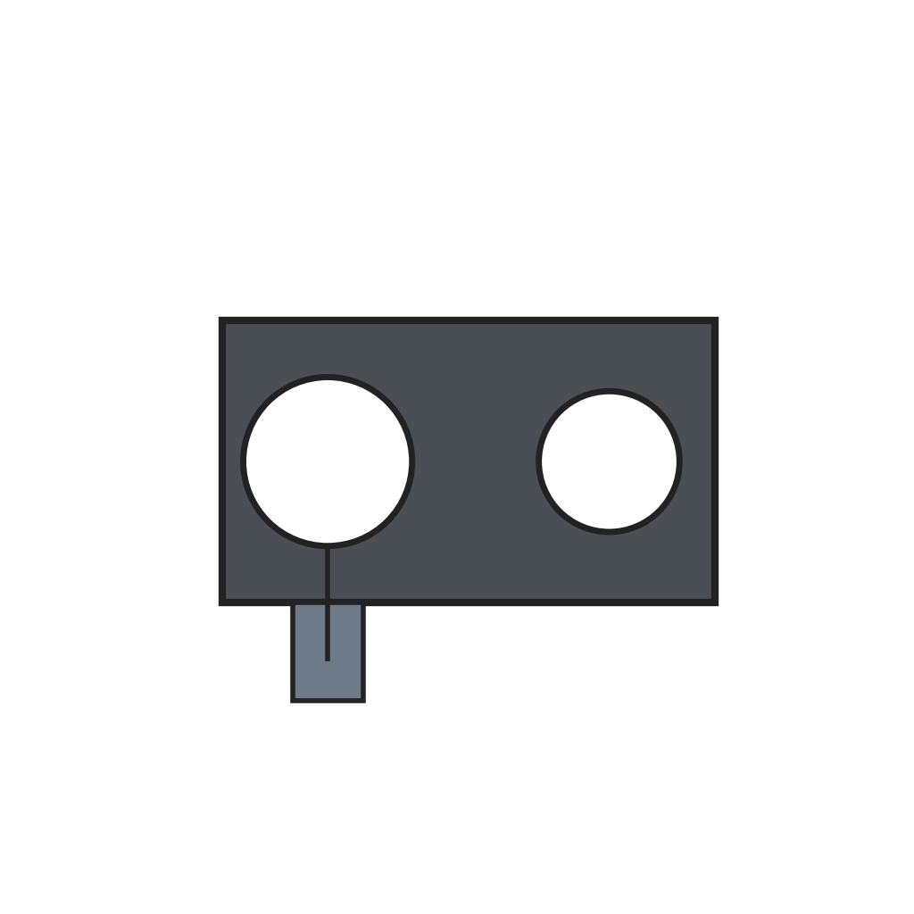
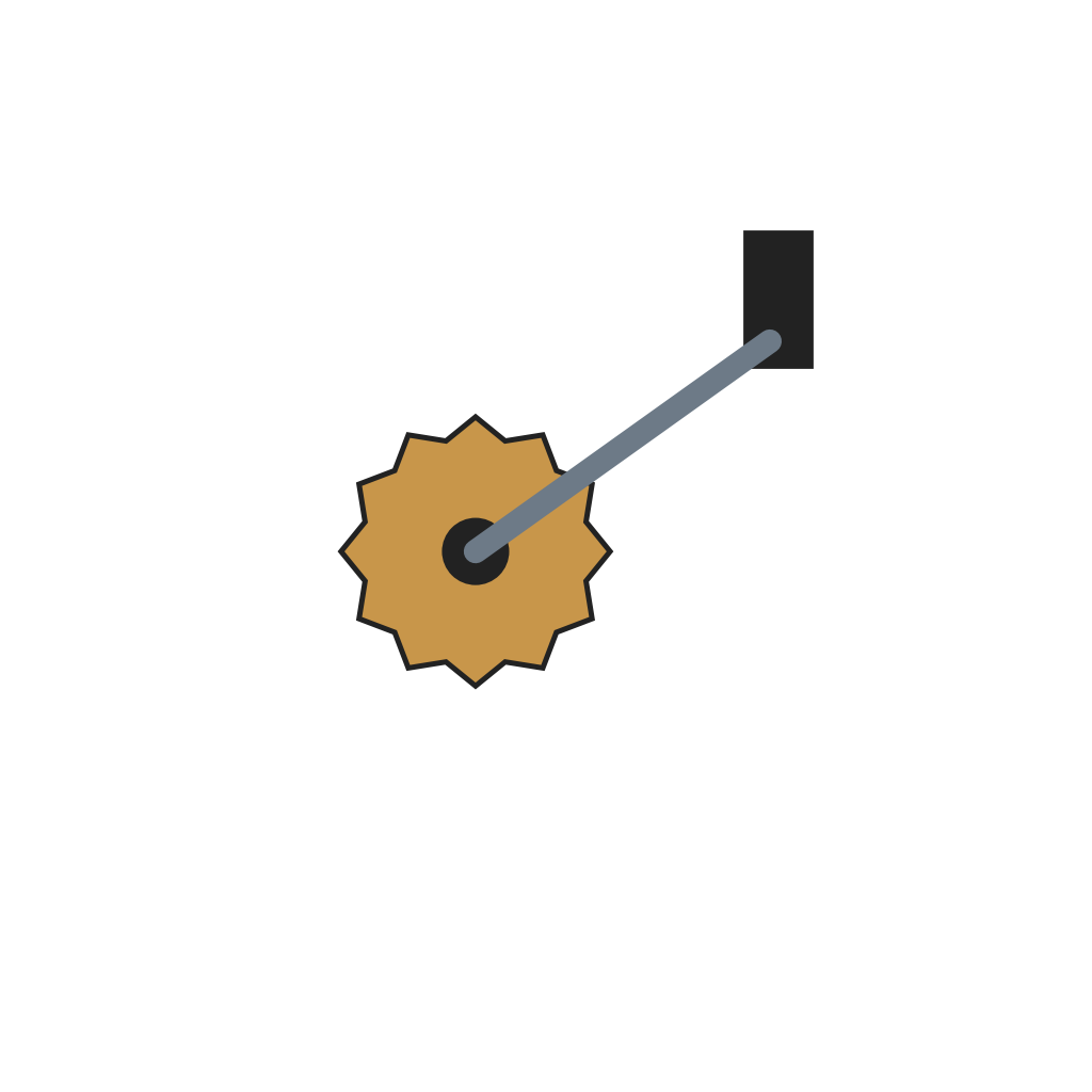
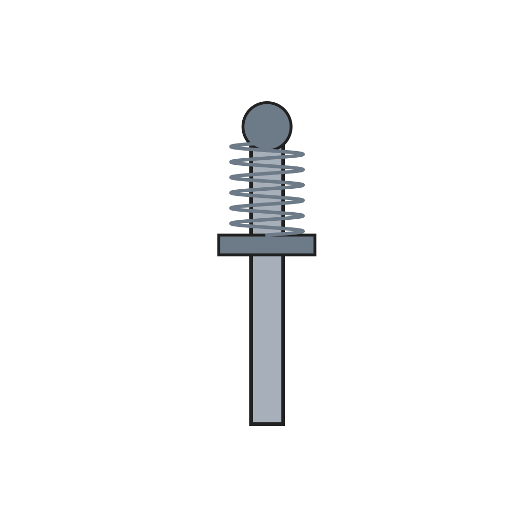
Make the head frame with a split C-section round the column, two clamping flanges and a slot through which the rack passes. A crank on the frame turns a pinion in the rack to raise and lower the head; a knobbed locking member through the flanges clamps the frame to the column. A spring-loaded indexing pin through a bracket on the rack drops into a bore in the column to lock the head over the centre of the base.

Materialien für diesen Schritt:

Bohrkopfrahmen mit geschlitzter SäulenklemmeBohrkopfrahmen mit geschlitzter Säulenklemme1 Stück
Kurbel und Ritzel zum Heben des BohrkopfsKurbel und Ritzel zum Heben des Bohrkopfs1 Stück
Federbelasteter RastbolzenFederbelasteter Rastbolzen1 Stück

Benötigte Werkzeuge:

Schraubendreher-SatzSchraubendreher-Satz
KombizangeKombizange
4

Motor and belt

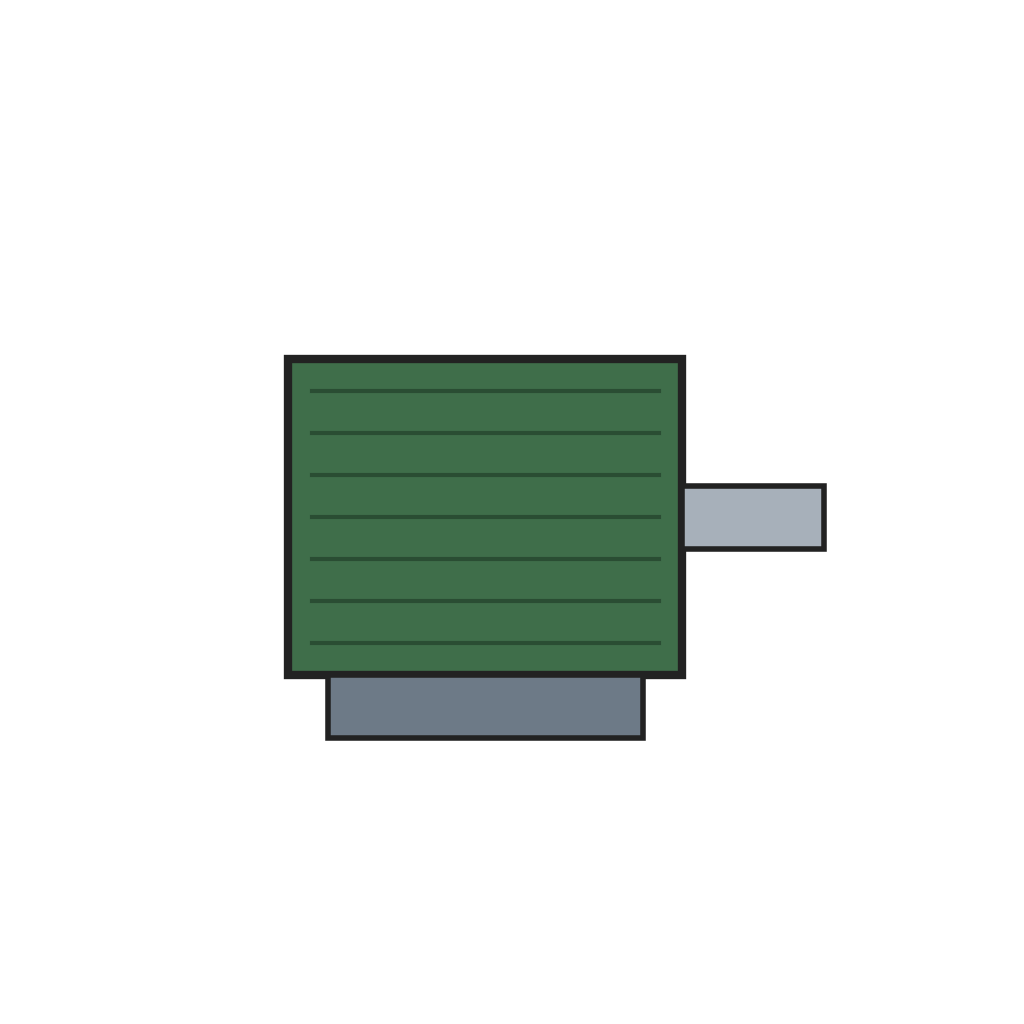
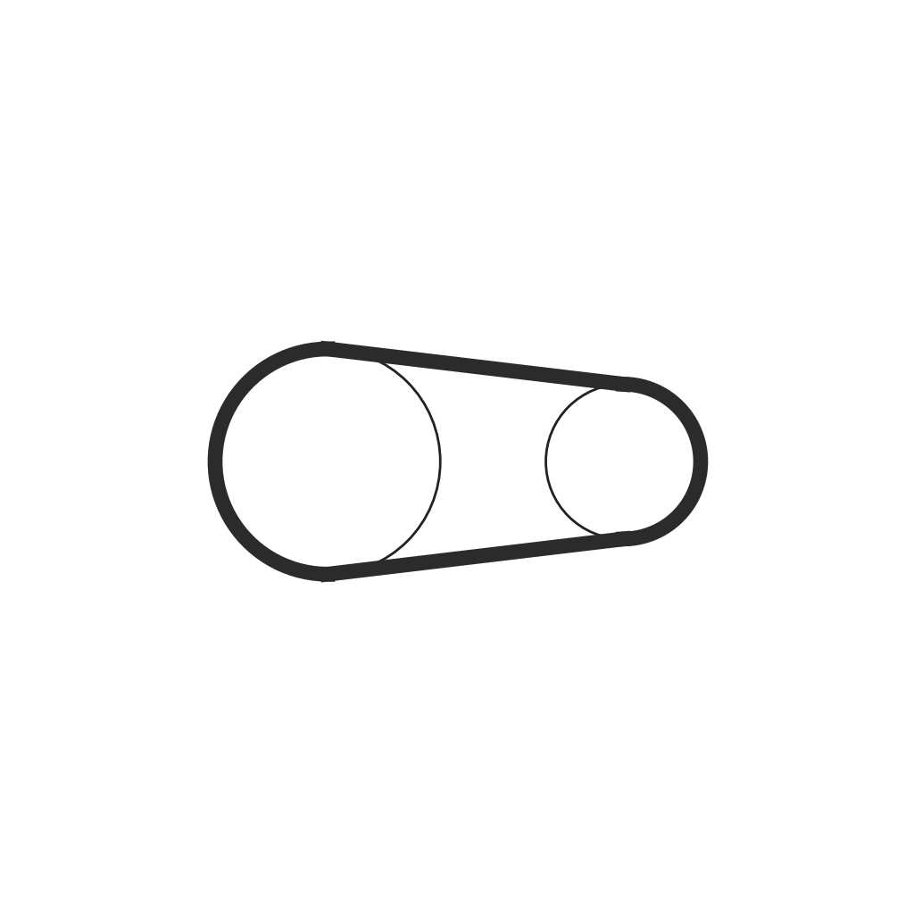
Mount the motor on a bracket that slides on a clamping rod and a parallel follower rod in a boss on the frame, on the opposite side of the column from the quill. A belt connects the motor to the quill; loosen the lock knob and slide the motor to tension the belt. A cover encloses the drive and its speed-change mechanism, with a clearance opening for the column. The on/off switch, speed control knob and light switch sit on the face of the frame.

Materialien für diesen Schritt:

ElektromotorElektromotor1 Stück
Verschiebbare MotorkonsoleVerschiebbare Motorkonsole1 Stück
AntriebsriemenAntriebsriemen1 Stück

Benötigte Werkzeuge:

RollgabelschlüsselRollgabelschlüssel
Schraubendreher-SatzSchraubendreher-Satz
5

Quill and chuck

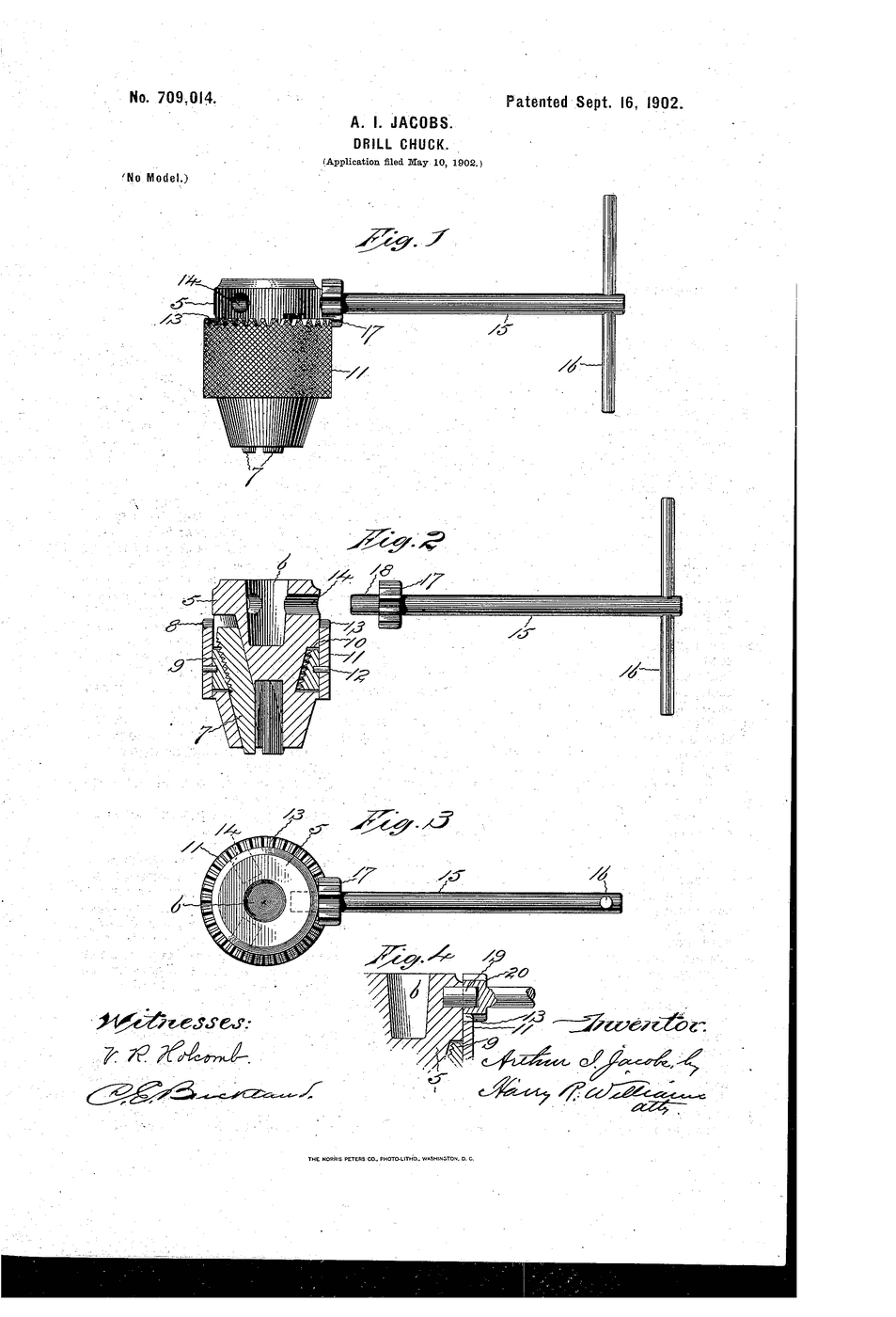
Fit the quill in the frame with a hand wheel that moves it up and down, and fit the chuck on its end to take the shanks of drill bits and other tools.

Materialien für diesen Schritt:

Bohrpinole mit Vorschub-HandradBohrpinole mit Vorschub-Handrad1 Stück
BohrfutterBohrfutter1 Stück

Benötigte Werkzeuge:

RollgabelschlüsselRollgabelschlüssel
6

Tilt table

Stamp and fold the supporting base from 3.2 mm steel plate, with a flat base, two upright trunnions, side walls, stiffener ribs and a longitudinal slot. Pivot the table frame between the trunnions on its two sector disks, and lay the particle board panel in it. Pass an eyebolt through the slot and the base's transverse slot, with a nylon nut underneath. An eccentric camshaft between the trunnions runs through the eye; turning its crank lifts the eyebolt and clamps the table to the base, and turning it back frees the table to slide or turn.

Materialien für diesen Schritt:

Tragsockel des NeigetischsTragsockel des Neigetischs1 Stück
BaustahlplatteBaustahlplatte1 Stück
Schwenkrahmen des NeigetischsSchwenkrahmen des Neigetischs1 Stück
Spanplatten-TischeinlageSpanplatten-Tischeinlage1 Stück
RingschraubeRingschraube1 Stück
NylonmutterNylonmutter1 Stück
Exzentrische KlemmnockenwelleExzentrische Klemmnockenwelle1 Stück

Benötigte Werkzeuge:
StanzpresseStanzpresse
RollgabelschlüsselRollgabelschlüssel

Materialien

18

Benötigte Werkzeuge

5

Verwandte Blueprints

Diese Blueprints teilen Wissen — Techniken, Materialien oder Prinzipien
CC0 Gemeinfrei

Dieser Blueprint ist unter CC0 veröffentlicht. Sie dürfen dieses Werk für jeden Zweck frei kopieren, ändern, verbreiten und verwenden, ohne um Erlaubnis zu fragen.

Unterstützen Sie den Maker, indem Sie Produkte über seinen Blueprint kaufen, wo er eine Maker-Provision von Anbietern festgelegt, verdient. Oder erstellen Sie eine neue Iteration dieses Blueprints und verbinden Sie ihn in Ihrem eigenen Blueprint, um Einnahmen zu teilen.

Diskussion

(0)

Anmelden um an der Diskussion teilzunehmen

Kommentare werden geladen...