Zusammenarbeit
KUNST
SCHÖNHEIT & WELLNESS
HANDWERK
KULTUR & GESCHICHTE
UNTERHALTUNG
UMFELD
ESSEN & GETRÄNKE
REVERSE ENGINEERING
WISSENSCHAFTEN
SPORT
TECHNOLOGIE
WEARABLES
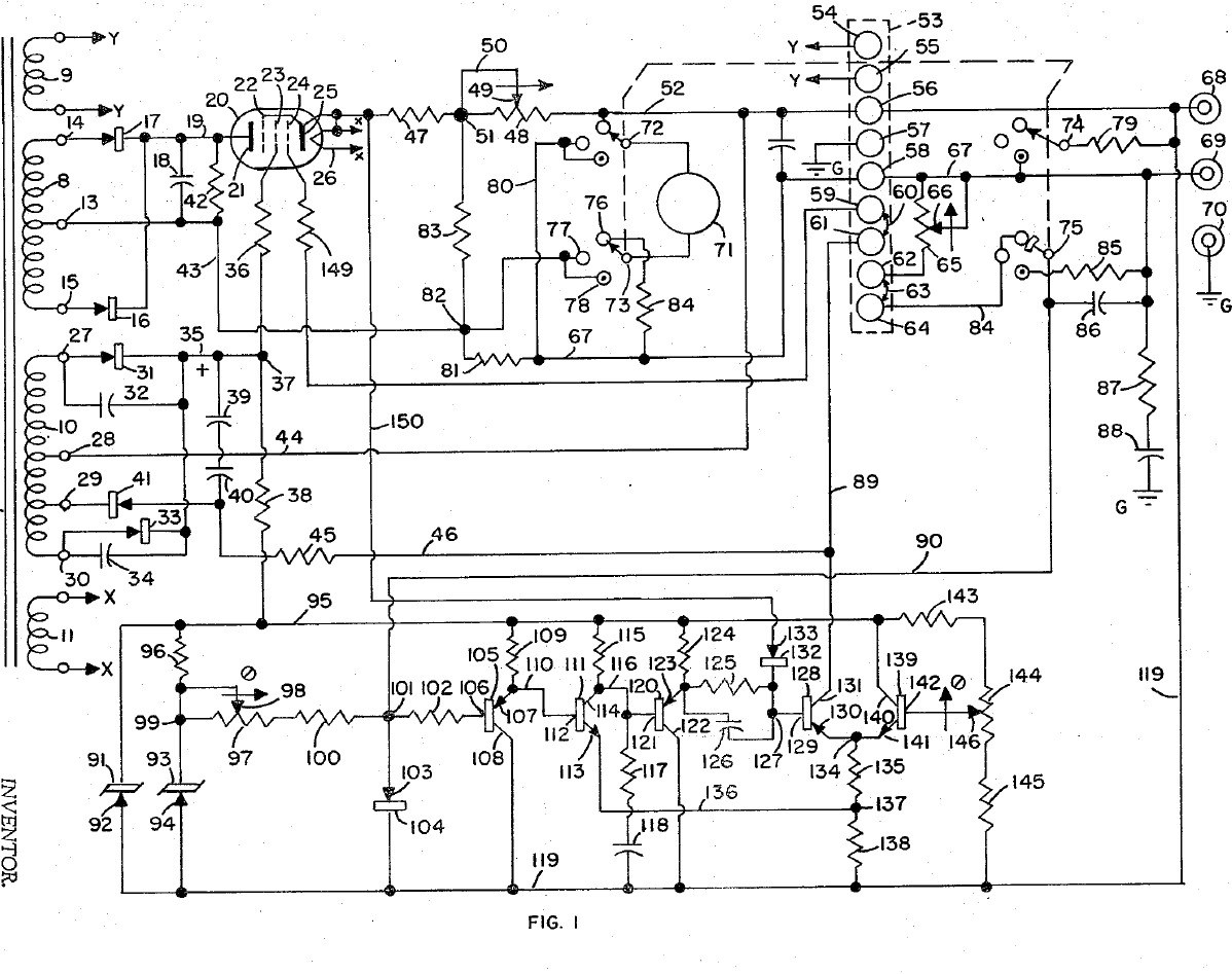


Bench Power Supply: Regulated, with Adjustable Current Limit and a Pentode Pass Tube (Gately, Forbro, US 3,243,690, 1966)
An adjustable bench supply that holds its output voltage steady and lets you set the most current it will deliver, so a circuit under test cannot be damaged. A pentode tube in series with the output is the regulator; a bridge with Zener references and a five-transistor amplifier keeps the output equal to the setting of one knob. A meter switch reads volts, amps, and the current limit, which can be set without disturbing the voltage.
Result: a regulated DC bench supply with adjustable current limiting.
Source: J. R. Gately (Forbro Design), US 3,243,690 (1966). Unknown: all component values and the output rating. Picture: the patent drawing.
Erfahren
Unknown
Anweisungen
1
1
Wire the mains side
Wire the mains side
In a case, wire the power cord through a switch and a fuse to the primary of a transformer with four secondaries, and put a neon lamp across the primary to show the supply is on. One secondary (6.3 V) goes to two terminals for outside use, one heats the pentode, one is the main supply and one the bias supply. Ours: the case. Not given: the other winding voltages.
Materialien für diesen Schritt:
 Aluminiumgehäuse1 case
 Anschlussleitung mit Stecker1 Stück
 Kippschalter1 Stück
 Schmelzsicherung1 Stück
 Abwärtstransformator1 four secondaries
 Neon-Glimmlampe1 Stück
 Polklemme2 6.3 V terminals
Benötigte Werkzeuge:
 Handbohrer
 Schraubendreher-Satz
2
2
Build the rectifiers
Build the rectifiers
Rectify the centre-tapped main winding with two rectifiers and smooth it with a capacitor. From the bias winding make two more supplies: one through two rectifiers with by-pass capacitors to a smoothing capacitor, for the pentode's screen and the reference circuit; the other through one rectifier and a capacitor, for the pentode's grid bias. Not given: the values.
Materialien für diesen Schritt:
 Diode5 rectifiers
 Elektrolytkondensator3 smoothing
 Kondensatorsortiment1 by-pass
 Lötdraht1 as needed
Benötigte Werkzeuge:
 Lötkolben
3
3
Fit the pass tube and reference
Fit the pass tube and reference
Put the pentode in series with the positive output: plate to the main supply, cathode through two current-sensing resistors (one fixed, one adjustable) to the + output terminal; suppressor tied to the cathode, screen fed through a resistor. Build the reference: a Zener fed through a resistor feeds a second Zener at constant current, giving a fixed voltage. Against it set two resistors and the voltage-control variable resistor: the output voltage is proportional to that resistor's setting. Not given: the tube type and values.
Materialien für diesen Schritt:
 Pentodenröhre1 series pass tube
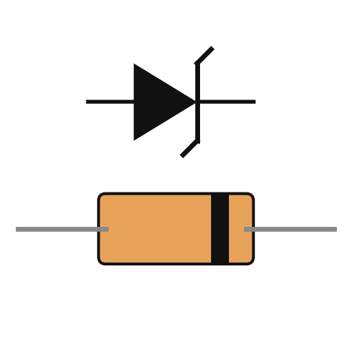 Z-Diode2 Stück
 Widerstand1 Set
 Regelwiderstand2 voltage control, current-limit rangePolklemme2 output + and -Lötdraht1 as needed
Benötigte Werkzeuge:
Lötkolben4
4
Build the error amplifier and current limit
Build the error amplifier and current limit
Build a five-transistor amplifier that drives the pentode's grid to keep the bridge balanced: a PNP emitter follower, an NPN stage, a PNP emitter follower with a resistor-capacitor roll-off against oscillation, a PNP driver whose base resistor has a capacitor across it for quick response, and an NPN clamp whose base is set by a potentiometer. Feed the voltage across the current-sensing resistors to the driver's base through a diode: above the limit it takes over and turns the pentode down. Choose the fixed sensing resistor to limit at about 125 % of rated current, trim with the potentiometer, and use the adjustable one to set lower limits. Not given: the transistor types and values.
Materialien für diesen Schritt:
 PNP-Transistor3 Stück
 NPN-Transistor2 StückDiode1 Stück
 Potentiometer1 StückKondensatorsortiment1 roll-off, speed-upWiderstand1 SetLötdraht1 as needed
Benötigte Werkzeuge:
Lötkolben5
5
Fit the meter and use it
Fit the meter and use it
Fit a meter with a four-pole, three-position switch. Position 1 reads output volts through a multiplier resistor; position 2 reads current across a shunt in the negative line; position 3 (spring-return) puts a load resistor across the output and swaps a fixed resistor for the voltage control, so you can turn the limit control until the current limits at the value you want, without touching the voltage setting. Release the switch and use the supply.
Materialien für diesen Schritt:
 Drehspul-Einbaumessgerät1 Stück
 Drehschalter1 4-pole, 3-positionWiderstand1 multiplier, shunt, load resistors
 Unbekanntes Material1 terminal strip
Benötigte Werkzeuge:
LötkolbenSchraubendreher-SatzMaterialien
21- 1 casePlatzhalter
- 1 StückPlatzhalter
- Platzhalter
- 1 StückPlatzhalter
- 1 four secondariesPlatzhalter
- 1 StückPlatzhalter
- Platzhalter
- 1 StückPlatzhalter
- 3 smoothingPlatzhalter
- 1 roll-off, speed-upPlatzhalter
- 3 as neededPlatzhalter
- 1 series pass tubePlatzhalter
- 2 StückPlatzhalter
- 1 multiplier, shunt, load resistorsPlatzhalter
- 2 voltage control, current-limit rangePlatzhalter
- 3 StückPlatzhalter
- 2 StückPlatzhalter
- Platzhalter
- 1 StückPlatzhalter
- 1 4-pole, 3-positionPlatzhalter
- 1 terminal stripPlatzhalter
Dieser Bauplan stellt her

CC0 Gemeinfrei
Dieser Blueprint ist unter CC0 veröffentlicht. Sie dürfen dieses Werk für jeden Zweck frei kopieren, ändern, verbreiten und verwenden, ohne um Erlaubnis zu fragen.
Unterstützen Sie den Maker, indem Sie Produkte über seinen Blueprint kaufen, wo er eine Maker-Provision von Anbietern festgelegt, verdient. Oder erstellen Sie eine neue Iteration dieses Blueprints und verbinden Sie ihn in Ihrem eigenen Blueprint, um Einnahmen zu teilen.