KUNST
SCHÖNHEIT & WELLNESS
HANDWERK
KULTUR & GESCHICHTE
UNTERHALTUNG
UMFELD
ESSEN & GETRÄNKE
REVERSE ENGINEERING
WISSENSCHAFTEN
SPORT
TECHNOLOGIE
WEARABLES
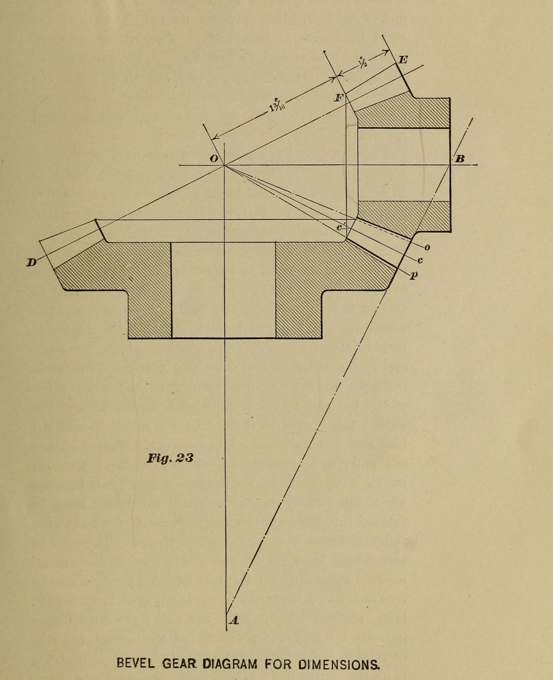


Bevel Pinion with a No. 6 Cutter, Filed at the Small End (Brown & Sharpe 1911)
The same 12-tooth, 8-pitch pinion as Brown & Sharpe's worked example, but cut the way their own shop did it: with a No. 6 cutter instead of the No. 8 they sell for it, cut to the right thickness at the large end, then filed well round at the small end. They did this only for a 12-tooth pinion running with a gear two or three times its size.
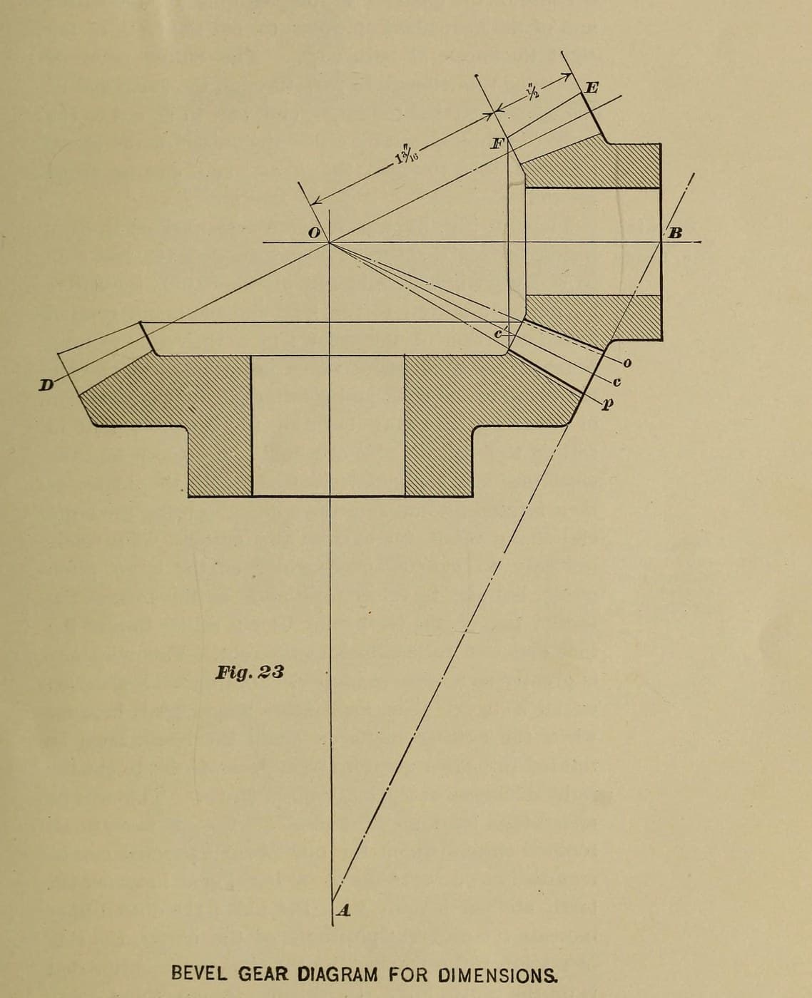
Source: Brown & Sharpe, Practical Treatise on Gearing (1911), Fig. 23 example, Part I ch. IX–X, Part II ch. III and the set-over table p. 58. The blank sizes are our arithmetic with their rules; the steel and bore are ours. Picture: their Fig. 23.
Erfahren
1 day
Anweisungen
1
1
Work out and turn the blank
Work out and turn the blank
Pitch diameter 12 ÷ 8 = 1.500 in. Angle of edge 26° 34′ and angle of face 59° 11′ (Brown & Sharpe's figures for every 12 and 24 tooth pair). Diameter increment = cos 26° 34′ × 0.250 = 0.224 in, so turn the steel blank to 1.72 in outside diameter. Face ½ in long. Try both angles with a protractor against the end of the hub.
Materialien für diesen Schritt:
 Baustahl-Flachstange1 length for one blank
Benötigte Werkzeuge:
 Metalldrehmaschine
 Drehmeißel
 Winkelmesser
 Mikrometer
2
2
Choose the cutter
Choose the cutter
Twice the back cone radius × 8 comes to about 13, which would call for a No. 8, but take a No. 6, 8-pitch bevel gear cutter (17 to 20 teeth), as Brown & Sharpe's own shop did for this pinion. Measure its thickness Tc at the pitch line, 0.145 in from its tip.
Benötigte Werkzeuge:
 Kegelradfräser
 Zahnweiten-Messschieber
3
3
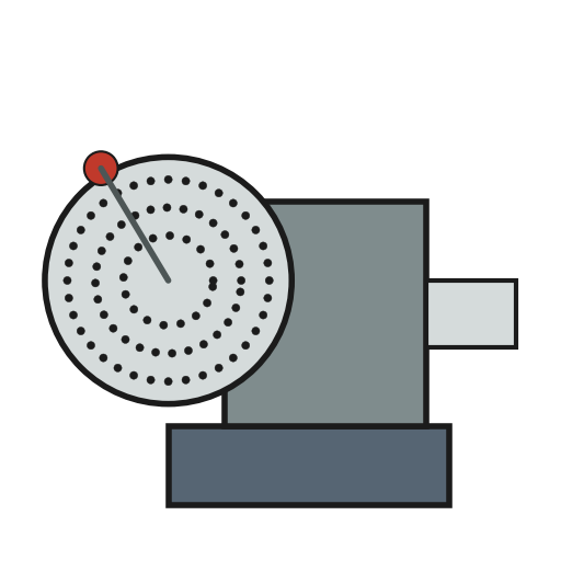
Set the head at 22° 18′
Set the head at 22° 18′
Apex distance = sec 26° 34′ × 1.5 = 1.677 in. Angle increment: tan = sin 26° 34′ ÷ 6, giving 4° 16′. Set the dividing head to the cutting angle 26° 34′ − 4° 16′ = 22° 18′ and index 12 spaces. Depth at the large end 0.270 in.
Benötigte Werkzeuge:
 Fräsmaschine
 TeilkopfKegelradfräser
4
4
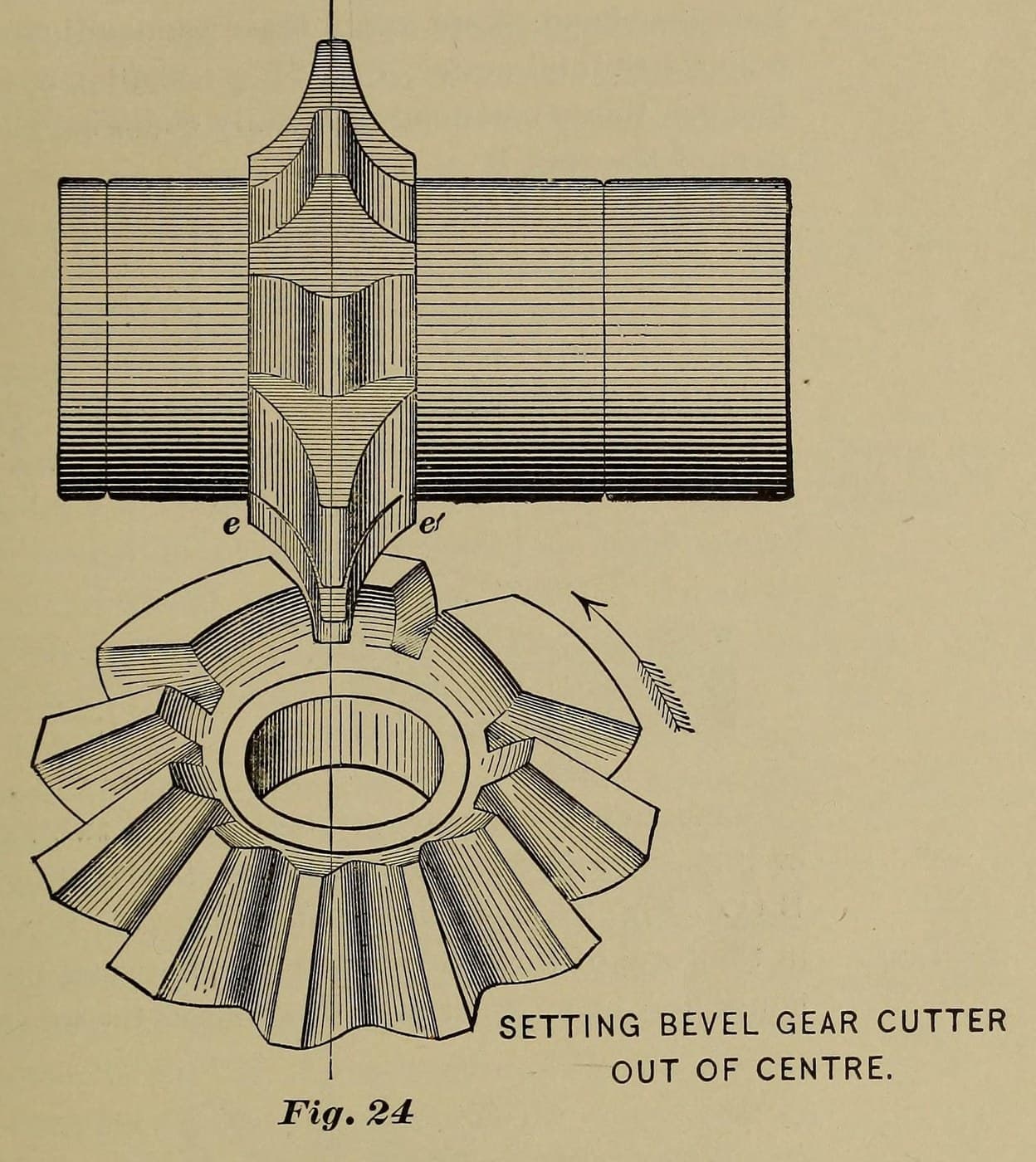
Set over and cut one side
Set over and cut one side
Apex distance ÷ face = 3.35; we take the nearest column, 3¼, where a No. 6 cutter has the factor .318. Set-over = Tc ÷ 2 − .318 ÷ 8 = Tc ÷ 2 − 0.040 in. Set off centre by that amount, take up backlash, and cut round all 12 spaces.
Benötigte Werkzeuge:
FräsmaschineTeilkopfKegelradfräser5
5
Set over the other way and trim
Set over the other way and trim
Set over the same amount the other side, line the cutter up with the space at the small end, take a trial cut, and rotate toward the cutter until the tooth is right at the faces of the large end: 0.196 in at the pitch line (0.138 in at the small end). Check with the gear tooth vernier, then cut round.
Benötigte Werkzeuge:
FräsmaschineTeilkopfKegelradfräserZahnweiten-Messschieber6
6
File the small ends
File the small ends
The No. 6 cuts the tooth sides with a longer curve than the No. 8, so expect considerable filing: round the teeth over at the small ends, without filing them thinner at the pitch line.
Benötigte Werkzeuge:
 Feine Feile
Materialien
1- 1 length for one blankPlatzhalter
Dieser Bauplan stellt her

Verwandte Blueprints
Diese Blueprints teilen Wissen — Techniken, Materialien oder Prinzipien
CC0 Gemeinfrei
Dieser Blueprint ist unter CC0 veröffentlicht. Sie dürfen dieses Werk für jeden Zweck frei kopieren, ändern, verbreiten und verwenden, ohne um Erlaubnis zu fragen.
Unterstützen Sie den Maker, indem Sie Produkte über seinen Blueprint kaufen, wo er eine Maker-Provision von Anbietern festgelegt, verdient. Oder erstellen Sie eine neue Iteration dieses Blueprints und verbinden Sie ihn in Ihrem eigenen Blueprint, um Einnahmen zu teilen.