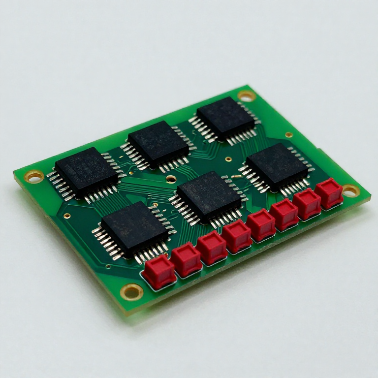


The Binary Adder
Anweisungen
Add two bits on paper and find the two outputs
Add two bits on paper and find the two outputs
Write out the only four cases and read the answer off.
- 0+0, 0+1, 1+0, 1+1 in binary.
- Note that the last one is 10 in binary — two digits.
- Tabulate the RIGHT digit (sum) and the LEFT digit (carry) separately.
- Compare each column with the truth tables from the relay blueprint.
The sum column is exactly XOR and the carry column is exactly AND. Nothing has been invented — arithmetic has been recognised as logic you already have.
That is the entire conceptual step, and it is worth not rushing past. Addition looked like a different kind of operation from AND and OR, and it is not. Once numbers are written in binary, arithmetic IS Boolean algebra, which is why a machine built from switches can do sums.
The awkward case is 1+1, because it needs two output digits where the inputs had one each. That overflow into a second digit is the carry, and every complication in the rest of this blueprint comes from moving it to the next column.Materialien für diesen Schritt:
 Millimeterpapier1 pad
Benötigte Werkzeuge:
 Rechner
Assemble the full adder from gates
Assemble the full adder from gates
Blockly-Arbeitsbereich
Loading Blockly workspace...
Benötigte Werkzeuge:
 Desktop-Computer
Build it in hardware and watch the carry ripple
Build it in hardware and watch the carry ripple
Wire four full adders in a row and catch the wrong answer on its way to being right.
- Build a 4-bit ripple-carry adder from logic ICs, with LEDs on every sum output and every carry.
- Set the inputs to 0111 + 0001 — a sum that forces a carry through every stage.
- Trigger the oscilloscope on the input change and watch the most significant sum bit.
- Measure the time from input change to the final output settling.
For a brief moment the output shows a wrong answer, then corrects, possibly several times, before settling. Those intermediate values are real voltages on real wires — the machine genuinely holds wrong results while the carry travels.
Measure the delay per stage and multiply: a 32-bit ripple adder is 32 gate delays deep, and the clock cannot tick faster than that. The adder sets the processor's speed limit.
This is why real processors do not use ripple carry. Carry-lookahead computes, from the inputs alone, whether each column will GENERATE a carry or PROPAGATE one arriving from below — so all carries are worked out in parallel instead of in sequence. It costs a great deal more logic and it removes the chain, and that trade has been made in essentially every processor since.Materialien für diesen Schritt:
 Logik-IC-Sortiment1 Set
 LED-Anzeigesatz2 Sets
 Widerstandssortiment1 Set
 Lochrasterplatine2 Stück
 Schaltdraht1 reel
Benötigte Werkzeuge:
 Lötstation
 Oszilloskop
 Digitalmultimeter, Laborqualität
 Regelbares Labornetzteil
Model the delay, and price carry-lookahead
Model the delay, and price carry-lookahead
Benötigte Werkzeuge:
Desktop-ComputerAdd an accumulator and you have arithmetic
Add an accumulator and you have arithmetic
Combine the two halves of this batch: an adder that computes and flip-flops that remember.
- Connect the sum outputs of your 4-bit adder to a register of four D-type flip-flops.
- Feed the register outputs back to one input of the adder.
- Put the number to be added on the other input, and pulse the clock.
- Pulse it repeatedly with 1 on the input and watch the register count.
The register now holds a running total, and each clock adds the input to it. That is an accumulator — the central component of every early computer, and the reason so many machines had exactly one place where arithmetic happened.
Notice what became possible the moment memory joined arithmetic: results can be fed back into the next operation, so a sequence of steps can build on each other. Without the register the adder answers one question; with it, the machine can work.
Watch the timing constraint bite. The register must not latch until the ripple carry has finished, or it stores a half-computed value — which is precisely why the adder's delay sets the clock speed, and why the flip-flop's setup time from the previous blueprint is not a detail but a hard constraint on the whole machine.Materialien für diesen Schritt:
Logik-IC-Sortiment1 SetLED-Anzeigesatz1 SetLochrasterplatine1 StückBenötigte Werkzeuge:
LötstationOszilloskop FunktionsgeneratorDigitalmultimeter, Laborqualität
Materialien
6- 1 padPlatzhalter
- 1 SetPlatzhalter
- 3 SetsPlatzhalter
- Platzhalter
- 3 StückPlatzhalter
- 1 reelPlatzhalter
Benötigte Werkzeuge
7- Platzhalter
- Platzhalter
- Platzhalter
- Platzhalter
- Platzhalter
- Platzhalter
- Platzhalter
Verwandte Blueprints
Diese Blueprints teilen Wissen — Techniken, Materialien oder Prinzipien

CC0 Gemeinfrei
Dieser Blueprint ist unter CC0 veröffentlicht. Sie dürfen dieses Werk für jeden Zweck frei kopieren, ändern, verbreiten und verwenden, ohne um Erlaubnis zu fragen.
Unterstützen Sie den Maker, indem Sie Produkte über seinen Blueprint kaufen, wo er eine Maker-Provision von Anbietern festgelegt, verdient. Oder erstellen Sie eine neue Iteration dieses Blueprints und verbinden Sie ihn in Ihrem eigenen Blueprint, um Einnahmen zu teilen.