KUNST
SCHÖNHEIT & WELLNESS
HANDWERK
KULTUR & GESCHICHTE
UNTERHALTUNG
UMFELD
ESSEN & GETRÄNKE
GRÜNE ZUKUNFT
REVERSE ENGINEERING
WISSENSCHAFTEN
SPORT
TECHNOLOGIE
WEARABLES
Übersetzt
BLUEPRINT NFT

Blinkende LED — Dein erstes Arduino-Projekt
Das klassische erste Elektronik-Projekt! Baue eine blinkende LED-Schaltung mit einem Arduino, einem Breadboard, einem Widerstand und einer einzelnen LED. Perfekt für absolute Anfänger — kein Löten erforderlich.
Anweisungen
1
1
Sammeln Sie Ihre Komponenten
Sammeln Sie Ihre Komponenten
Sammeln Sie alle unten aufgeführten Komponenten. Kein Löten erforderlich – alles wird auf das Breadboard gesteckt.
Materialien für diesen Schritt:
 SparkFun Inventor's Kit - V3.21 Set
Arduino Uno R31 Stück
5mm LED (any color)1 Stück
 220 ohm Resistor (1/4W)1 Stück
Breadboard1 Stück
Jumper Wires (Male-to-Male)2 Stück
USB-B Cable1 Stück
Benötigte Werkzeuge:
Computer with Arduino IDE
2
2
Schaltplan
Schaltplan
Das Signal fließt von Arduino Pin 13 → 220Ω Widerstand (R1) → LED (D1) → GND. Der Widerstand begrenzt den Strom zum Schutz der LED.
Materialien für diesen Schritt:
Arduino Uno R31 Stück
5mm LED (any color)1 Stück
220 ohm Resistor (1/4W)1 Stück3
3
Verdrahten Sie es
Verdrahten Sie es
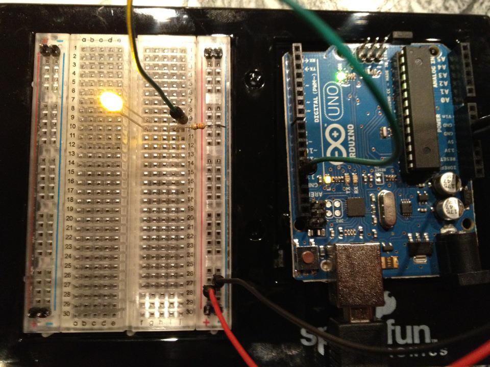
- Stecken Sie die LED in das Breadboard — langes Bein (Anode +) in eine Reihe, kurzes Bein (Kathode −) in die nächste.
- Stecken Sie ein Bein des 220Ω-Widerstands in die gleiche Reihe wie die LED-Kathode. Anderes Bein in eine separate Reihe.
- Jumper-Draht von LED-Anode-Reihe → Arduino Pin 13.
- Jumper-Draht von Widerstand-freier Reihe → Arduino GND.
Materialien für diesen Schritt:
5mm LED (any color)1 Stück
220 ohm Resistor (1/4W)1 StückBreadboard1 Stück
Jumper Wires (Male-to-Male)2 Stück
4
4
Den Blink-Code hochladen
Den Blink-Code hochladen
Arduino über USB verbinden. Arduino IDE öffnen, Tools → Board → Arduino Uno auswählen, den Code einfügen und auf Upload klicken.
blink.inoarduino
Materialien für diesen Schritt:
Arduino Uno R31 Stück
USB-B Cable1 Stück
Benötigte Werkzeuge:
Computer with Arduino IDE
5
5
PCB Layout (Referenz)
PCB Layout (Referenz)
Dies zeigt die Schaltung als PCB Layout. Nicht notwendig für dieses Projekt — das Steckbrett funktioniert perfekt — aber zeigt, wie die gleiche Schaltung aussehen würde, wenn sie als echte Platine hergestellt würde.
6
6
Test und Experiment
Test und Experiment
LED blinkt? Glückwunsch! Du hast gerade Hardware programmiert.
Fehlerbehebung:
Nächste Experimente:
Fehlerbehebung:
- LED leuchtet nicht auf? Drehe LED um — langes Bein zu Pin 13.
- LED bleibt an? Überprüfe, ob der Code erfolgreich hochgeladen wurde.
- Nichts passiert? Überprüfe, ob die Verkabelung dem Schaltplan in Schritt 2 entspricht.
Nächste Experimente:
- Ändere
delay()-Werte, um die Blinkgeschwindigkeit zu steuern - Füge eine zweite LED an Pin 12 hinzu
- Ersetze durch einen RGB LED (siehe SIK Schaltung 3)
Materialien
7- €90.00
- Platzhalter
Geschätzte Gesamtkosten
€90.00Related blueprints
Other builds that share materials, tools, or techniques with this one.

Using a Shift Register — SIK Circuit 14electronics/active
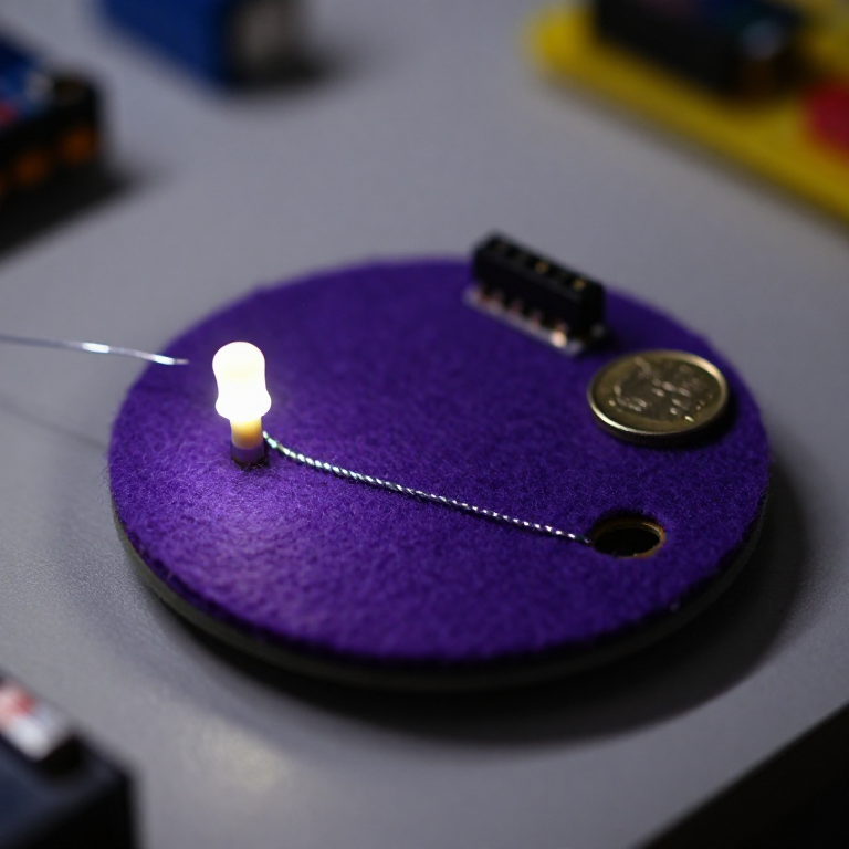
Blinking an LED with LilyPad Arduinoelectronics

Making Charcoal — The First Chemical Processmaterials

The Spinning Jenny — Multi-Spindle Yarn Productiontextiles

Starting Seeds Indoors — Raising Seedlings for a Head Start

Driving a Motor — SIK Circuit 12electronics/electromech
CC0 Gemeinfrei
Dieser Blueprint ist unter CC0 veröffentlicht. Sie dürfen dieses Werk für jeden Zweck frei kopieren, ändern, verbreiten und verwenden, ohne um Erlaubnis zu fragen.
Unterstützen Sie den Maker, indem Sie Produkte über seinen Blueprint kaufen, wo er eine Maker-Provision von Anbietern festgelegt, verdient. Oder erstellen Sie eine neue Iteration dieses Blueprints und verbinden Sie ihn in Ihrem eigenen Blueprint, um Einnahmen zu teilen.