Zusammenarbeit
KUNST
SCHÖNHEIT & WELLNESS
HANDWERK
KULTUR & GESCHICHTE
UNTERHALTUNG
UMFELD
ESSEN & GETRÄNKE
REVERSE ENGINEERING
WISSENSCHAFTEN
SPORT
TECHNOLOGIE
WEARABLES
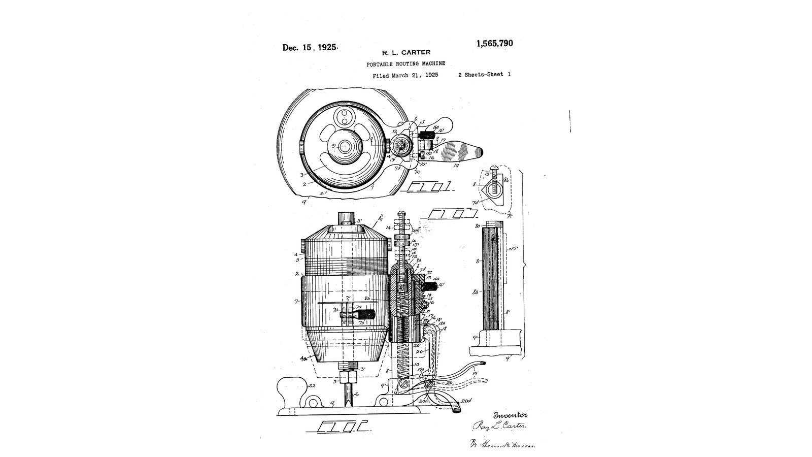


Rack-and-Pawl Plunge Router: The Motor Rides One Post on a Spring and Steps Down a Tooth at a Time (Carter, 1925)
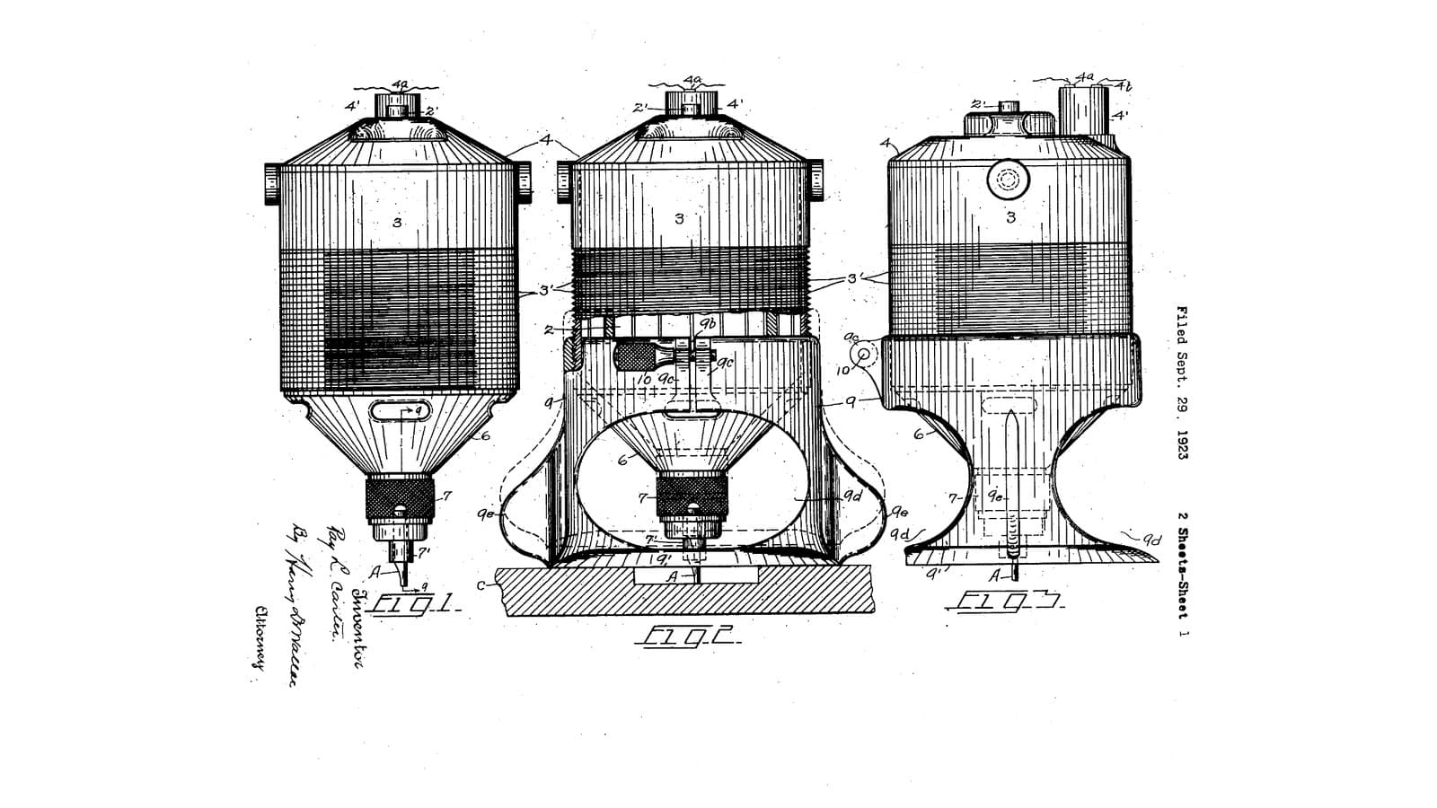
Ray L. Carter of Syracuse, New York, improved his 1924 router with US 1,565,790, dated 15 December 1925. The motor's holder now slides up and down a single strong post on a large round base, and a spring inside the post holds it up off the work. Each press of a lever moves the holder down one tooth of a rack, so a deep cavity is cut in stages. A locking pawl holds each step. Gauge nuts on a plunger stem set the final depth, and pressing the pawl's foot lets the spring lift the cutter clear.
We reuse our 1924 router's printed motor casing in a printed holder on a square steel post. The sizes are ours.
Erfahren
About 3 days
Anweisungen
1
1
Cutting deep in stages
Cutting deep in stages
Jupyter-Notebook wird geladen …
2
2
Read US 1,565,790
Read US 1,565,790
"By this arrangement cavities of considerable depth may be routed by successive stages wherein each stage represents the normal depth the tool is designed to cut."
3
3
The motor and its casing come from the 1924 router
The motor and its casing come from the 1924 router
Print the casing and fit the motor, collet and switch exactly as in Carter's 1924 router; here the casing screws into a holder on a post instead of into a base.
4
4
Print the holder
Print the holder
The holder 7: a split ring threaded for the 1924 casing, clamp lugs for a thumb screw, and beside it the guide 7c with a square opening for a 1 in tube, a recess for the gib plate, two set-screw holes and the rack 17 of 3 mm teeth on its outer face. Print it rack upright. PETG, 0.2 mm layers, 40 % infill, 5 walls; no supports.
5
5
Print the base
Print the base
The base 9: a round plate 170 mm across with a 50 mm opening, and the boss 9' with a square socket for the post and a hole for its cross bolt. Print it plate down. PETG, 0.2 mm layers, 40 % infill, 5 walls; no supports.
6
6
The hollow post 8
The hollow post 8
Cut 1 inch square steel tube 200 mm long. Saw and file a slot 8b 6 mm wide and 100 mm long down the middle of one wall, starting 40 mm from the top. Push the post into the base's socket and bolt it through with an M6 bolt and lock nut. Drop a compression spring 10 into the post, then a plunger 13: a block of flat bar that slides in the tube, tapped M6 on its back for the screw that runs in the slot, with an M6 rod 13' standing up from it. Screw a flat-bar cap 12 across the post's top with a hole for the rod, and run two gauge nuts 14, 14' onto the rod above it.
Materialien für diesen Schritt:
 Mild Steel Square Tube 1" x 1"1 Stück
 Baustahl-Flachstahl1 Stück
 Druckfedernsortiment1 Stück
 Gewindestange1 Stück
 Sechskantmutter2 Stück
 Sechskantschrauben-Sortiment3 Stück
 Sicherungsmutter mit Kunststoffeinsatz1 Stück
Benötigte Werkzeuge:
 Bügelsäge (Metallsäge)
 Feilensatz
 Schraubstock
 Standbohrmaschine
 Bohrersatz
 Gewindeschneidsatz
 Windeisen
 Rollgabelschlüssel
 Schutzbrille
7
7
Holder on the post
Holder on the post
Print the holder and base. Lay a strip of flat bar in the guide's recess 15 as the gib plate 15' and run two M5 set screws 16 against it, one with a wing nut on its head to lock the holder by hand. Slide the guide down over the post and fix it to the plunger with an M6 screw through the slot. Set the screws so the holder slides freely without rattling. Screw the 1924 motor casing into the holder and lock it with an M5 screw and wing nut through the lugs.
Materialien für diesen Schritt:
 PETG-Filament1 StückBaustahl-Flachstahl1 Stück
 Madenschraube mit Ringschneide2 Stück
 Handflügelmutter2 Stück
 Zylinderschraube mit Innensechskant2 Stück
Benötigte Werkzeuge:
 FDM-3D-Drucker
 Entgrater
 Innensechskant-Schlüsselsatz
 Digitaler Messschieber 6 Zoll
8
8
Pawls and lever
Pawls and lever
File a pawl 18 from flat bar with a hook 18' at its top to catch the rack's teeth, and a locking pawl 20 with a tooth 20' at its top and its lower end bent out as a foot 20d. Pivot the locking pawl on the base's boss with an M5 screw, held against the rack by a spring-steel leaf 20b. Pivot one end of a lever 19 on the boss and the pawl's lower end to the lever partway along, with a second leaf 20c holding the pawl to the rack. Each press of the lever's handle pulls the holder down one tooth, and the locking pawl drops in under it.
Materialien für diesen Schritt:
Baustahl-Flachstahl2 Stück Federstahlband1 StückZylinderschraube mit Innensechskant3 StückSicherungsmutter mit Kunststoffeinsatz3 Stück
Benötigte Werkzeuge:
Bügelsäge (Metallsäge)FeilensatzSchraubstockStandbohrmaschineBohrersatzRollgabelschlüssel9
9
Rout a deep recess
Rout a deep recess
Fit a straight bit. Set the gauge nuts so the plunger's rod stops on the cap at the depth wanted. Clamp a board, rest the base on it with the cutter clear, switch on, press the lever once and move the router across the area; press again and repeat, until the nuts stop it. Press the locking pawl's foot and the spring lifts the cutter out.
Benötigte Werkzeuge:
 Fräsersatz
 Hartholzbrett
 Schraubzwinge mit SchiebebügelSchutzbrille
10
10
Troubleshooting
Troubleshooting
Plunge router troubleshooting.
Flow
Loading...
11
11
History and honest limits
History and honest limits
**Ray L. Carter** of Syracuse, New York, US 1,565,790, dated 15 December 1925, filed 21 March 1925, improving his US 1,514,894. He describes a holder "formed at one side with a guide portion having an angular vertical opening, for slidably mounting the holder upon a pedestal or post of substantially the same angularity", a coil spring housed in the pedestal, a ratchet rack and pawl to move the motor step by step, a locking pawl, gauge nuts, and a plate with set screws to take up wear. His post is triangular and cast; ours is 1 inch square steel tube. His holder and base are metal; ours are printed PETG. His motor ran on mains; ours is the small DC motor of our 1924 router. The sizes are ours.
Materialien
12- Platzhalter
- 2 StückPlatzhalter
- 1 StückPlatzhalter
- 1 StückPlatzhalter
- 2 StückPlatzhalter
- 3 StückPlatzhalter
- Platzhalter
- 1 StückPlatzhalter
- Platzhalter
- 2 StückPlatzhalter
- Platzhalter
- 1 StückPlatzhalter
Benötigte Werkzeuge
16- Platzhalter
- Platzhalter
- Platzhalter
- Platzhalter
- Platzhalter
- Platzhalter
- Platzhalter
- Platzhalter
- Platzhalter
- Platzhalter
- Platzhalter
- Platzhalter
- Platzhalter
- 1 vendor sell this, none ship to you yetPlatzhalter
- Platzhalter
- Platzhalter
Designdateien
2Dieser Bauplan stellt her

Verwandte Blueprints
Diese Blueprints teilen Wissen — Techniken, Materialien oder Prinzipien
CC0 Gemeinfrei
Dieser Blueprint ist unter CC0 veröffentlicht. Sie dürfen dieses Werk für jeden Zweck frei kopieren, ändern, verbreiten und verwenden, ohne um Erlaubnis zu fragen.
Unterstützen Sie den Maker, indem Sie Produkte über seinen Blueprint kaufen, wo er eine Maker-Provision von Anbietern festgelegt, verdient. Oder erstellen Sie eine neue Iteration dieses Blueprints und verbinden Sie ihn in Ihrem eigenen Blueprint, um Einnahmen zu teilen.