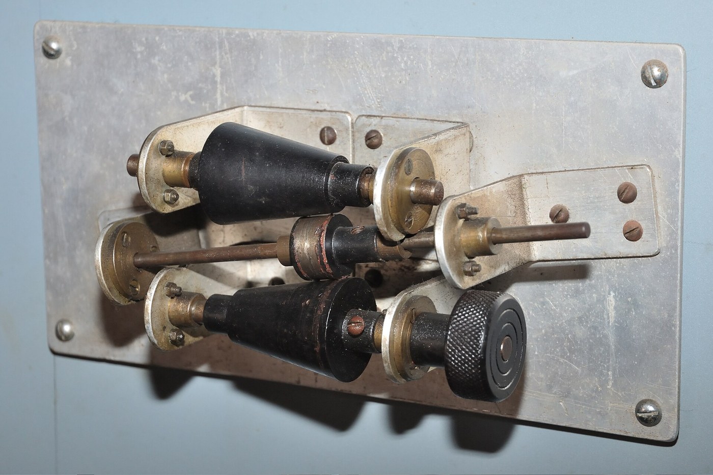


Cone Clutch
Anweisungen
Choose the taper angle deliberately
Choose the taper angle deliberately
One angle decides whether the clutch works, needs a hydraulic ram, or refuses to let go.
- Set out a 12 degree half-angle cone on paper at full size.
- Mark the engagement diameter at 60 mm and the cone length at 30 mm.
- Note the relationship: normal force ≈ axial force ÷ sin(half-angle).
- At 12 degrees, sin is about 0.21, so the faces see roughly 5 times your push.
Why not go shallower for more multiplication? Below about 8 degrees the cone self-locks — friction on the taper exceeds the component trying to push it out, so the clutch stays engaged after you release the lever and must be levered apart. Above about 15 degrees the multiplication falls away and you need a heavy spring. Twelve degrees sits in the usable band, and that band is narrow.
Write the angle on both parts as you make them. A male cone at 12 degrees in a female at 14 contacts on one edge only, and the clutch will grip weakly then wear rapidly at that line.Materialien für diesen Schritt:
 Millimeterpapier1 pad
Benötigte Werkzeuge:
 Kombinationswinkel
 Digitaler Messschieber 6 Zoll
Make the matched cone pair
Make the matched cone pair
Cut both from the same setup if you possibly can — matched tapers are the whole job.
- From 25 mm aluminium round bar, cut a male cone body 60 mm long and file the 12 degree taper.
- Cut a female housing from the same bar and bore the matching internal taper.
- Bore both centres 8.0 mm for their shafts.
- Blue the male cone and push it into the female — the transfer should show contact along the whole face, not just at one end.
- File and re-test until contact is even.
What the patent-era clutches used: a cast iron cone faced with leather, cork or woven asbestos, because the facing gives a higher and more stable friction coefficient than metal on metal and wears in preference to the expensive part. Modern build spec (derived): bare aluminium for the demonstration, or glue a strip of leather to the male cone for a marked improvement in grip.
The blue transfer test here is the same technique as the three-plate method — contact patterns tell you what a measurement cannot.Materialien für diesen Schritt:
 Aluminium-Rundstange2 Stück
Benötigte Werkzeuge:
 Sägebügel mit Sägeblättern
 Schraubstock
 Feilensatz
 Akkubohrschrauber
 BohrersatzDigitaler Messschieber 6 Zoll
Mount both shafts and add the engagement lever
Mount both shafts and add the engagement lever
The male cone must slide along its shaft while still driving it.
- Mount both shafts in 608 bearings in plywood pillow blocks, fixed with M5 × 40 socket head cap screws × 4, M5 flat washers × 8 and M5 hex nuts × 4.
- Cut a key slot along the male shaft, or file a flat, so the cone slides axially but cannot rotate on it.
- Fit an M5 cup point set screw in the cone running in that slot.
- Make a fork lever engaging a groove in the cone's back face, pivoted on an M6 × 40 hex bolt.
- Fit a compression spring behind the cone so it defaults to ENGAGED.
Why spring-engaged rather than spring-released. If the operator lets go, or a linkage breaks, a spring-engaged clutch stays connected and the machine keeps driving; a spring-released one disconnects. Which default is safer depends entirely on the machine, and it is a decision worth making deliberately rather than by accident of layout.
The sliding-but-driving joint is the fiddly part. A flat on the shaft with a set screw riding on it is the simplest version and perfectly adequate here.Materialien für diesen Schritt:
 Sperrholzplatte1 Blatt
 Kugellager4 Stück
 Unterlegscheibe8 Stück
 Sechskantmutter4 Stück
 Madenschraube mit Ringschneide2 Stück
 Druckfedernsortiment1 Set
Benötigte Werkzeuge:
AkkubohrschrauberBohrersatz Innensechskantschlüssel-SatzFeilensatz
 Laubsäge (Schweifsäge)Kombinationswinkel
Measure the multiplication, and the slip
Measure the multiplication, and the slip
Two numbers turn this from a demonstration into data.
- Hang a known weight on the engagement lever to produce a measured axial force.
- Wrap a cord round the output shaft and find the load at which it begins to slip.
- Compute the transmitted torque, then repeat at double the axial force.
- Now spin the input by hand and engage — note the moment of slip before speeds match.
Benötigte Werkzeuge:
Digitaler Messschieber 6 Zoll Stoppuhr
History and where it belongs
History and where it belongs
Cone clutches were everywhere in early machinery and early cars, often leather-faced, because they deliver a lot of torque for a simple, compact part with one moving element. They were largely displaced in automobiles by the multi-plate and single-plate dry clutch, which spreads the same friction over more area in less axial length and is easier to cool.
They did not disappear. Cone synchronisers in every manual gearbox are cone clutches — small brass or friction-lined cones that spin the next gear up to speed before the dog teeth engage. So the modern gearbox uses BOTH approaches deliberately: the cone clutch to match speeds gently, then the dog clutch to lock positively. That combination is the direct answer to the trade-off in this batch.
The self-locking limit is real and worth respecting. The same wedging that makes shallow tapers grip hard is what makes Morse taper tool holders stay in a spindle without a drawbar — there, self-locking is the FEATURE. Same geometry, opposite intent, and the dividing line is the friction angle of the materials.
Against its siblings: the dog clutch cannot slip and so cannot be engaged at speed. The centrifugal clutch needs no operator at all but engages only at its designed speed. The cone clutch engages at any speed and slips under overload — forgiving, but it wears, and a worn clutch transmits less torque than it did when new.
Materialien
8- 1 padPlatzhalter
- 2 StückPlatzhalter
- 1 BlattPlatzhalter
- Platzhalter
- 8 StückPlatzhalter
- 4 StückPlatzhalter
- Platzhalter
- 1 SetPlatzhalter
Benötigte Werkzeuge
10- Platzhalter
- Platzhalter
- Platzhalter
- Platzhalter
- Platzhalter
- 1 vendor sell this, none ship to you yetPlatzhalter
- Platzhalter
- Platzhalter
- Platzhalter
- Platzhalter
Verwandte Blueprints
Diese Blueprints teilen Wissen — Techniken, Materialien oder Prinzipien
CC0 Gemeinfrei
Dieser Blueprint ist unter CC0 veröffentlicht. Sie dürfen dieses Werk für jeden Zweck frei kopieren, ändern, verbreiten und verwenden, ohne um Erlaubnis zu fragen.
Unterstützen Sie den Maker, indem Sie Produkte über seinen Blueprint kaufen, wo er eine Maker-Provision von Anbietern festgelegt, verdient. Oder erstellen Sie eine neue Iteration dieses Blueprints und verbinden Sie ihn in Ihrem eigenen Blueprint, um Einnahmen zu teilen.