

Digital Spirit Level
Anweisungen
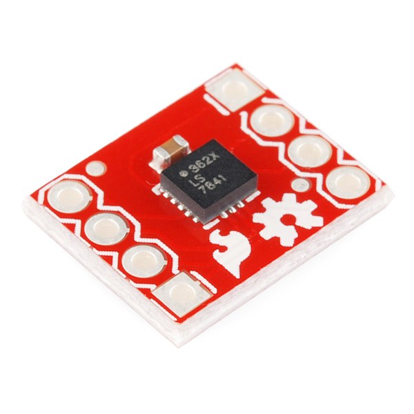
Solder headers to the accelerometer and level converter
Solder headers to the accelerometer and level converter
Fit breakaway headers to both boards so they seat in the breadboard. Both are small-pitch parts — keep the iron brief so a pad does not lift.
Materialien für diesen Schritt:
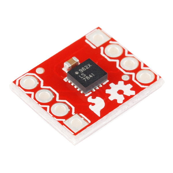 Triple Axis Accelerometer Breakout - ADXL3621 Stück
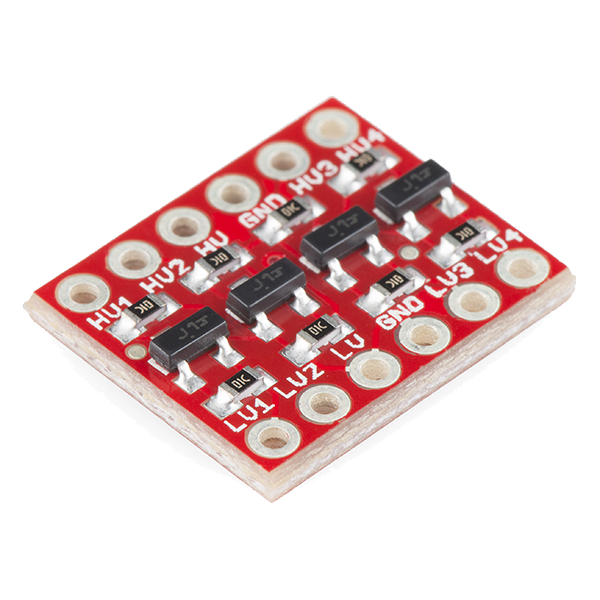 SparkFun Logic Level Converter - Bi-Directional1 Stück
Benötigte Werkzeuge:
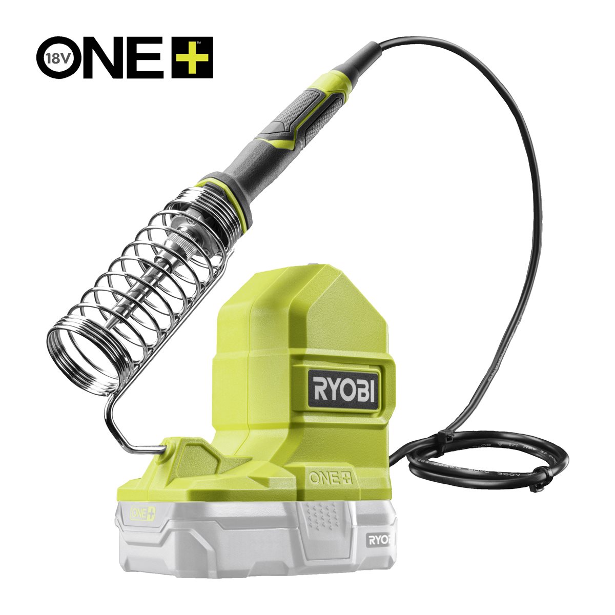 Ryobi ONE+ RSI18-0 Cordless Soldering Iron
Wire the accelerometer through the level converter — pin by pin
Wire the accelerometer through the level converter — pin by pin
The converter has a low-voltage side (LV) and a high-voltage side (HV). The accelerometer is on LV, the Arduino on HV.
- Converter LV → Arduino 3.3V; converter HV → Arduino 5V; both GND rails common.
- ADXL362 VIN → Arduino 3.3V, ADXL362 GND → GND.
- ADXL362 SCLK → LV1 · HV1 → Arduino D13
- ADXL362 MOSI → LV2 · HV2 → Arduino D11
- ADXL362 MISO → LV3 · HV3 → Arduino D12
- ADXL362 CS → LV4 · HV4 → Arduino D10
Materialien für diesen Schritt:
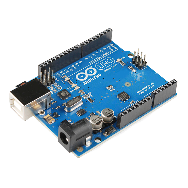 Arduino Uno R3 SMD1 Stück
 Breadboard - Classic1 Stück
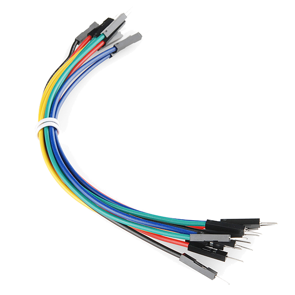 Jumper Wires Premium M/M 20 AWG - 15.5 cm (Pack of 10)1 Packung
Wire the display and set its contrast
Wire the display and set its contrast
Wire the 16x2 display in 4-bit parallel mode. It is a 5 V part and connects straight to the Arduino — it does not go through the converter.
- LCD RS → D7, E → D6
- LCD D4 D5 D6 D7 → Arduino D5 D4 D3 D2
- LCD RW → GND, VSS → GND, VDD → 5V
- A 10 kΩ potentiometer across 5V and GND, wiper → LCD V0
Materialien für diesen Schritt:
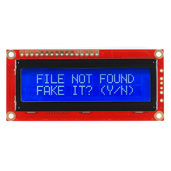 Basic 16x2 Character LCD - 5V1 Stück
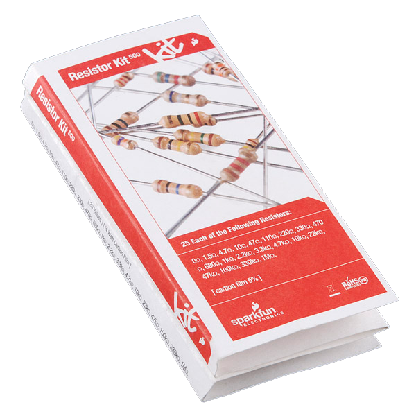 Resistor Kit - 1/4W (500 total)1 Set
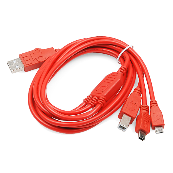 USB-B Cable1 Stück
Upload the level sketch
Upload the level sketch
Talks to the ADXL362 over raw SPI so every register write is visible rather than hidden in a library. SPI and LiquidCrystal ship with the IDE.
Zero it, then prove it with the reversal test
Zero it, then prove it with the reversal test
Lay the board on a surface you are treating as flat. It zeroes itself at power-up, so it will read close to 0.0.
- Turn the board end for end on the same surface.
- A correctly zeroed level now reads the same magnitude with the opposite sign.
Materialien
8- Triple Axis Accelerometer Breakout - ADXL36210% Provision1 Stück€12.40
- SparkFun Logic Level Converter - Bi-Directional10% Provision1 Stück€3.10
- Arduino Uno R3 SMD10% Provision1 Stück€23.55
- Breadboard - Classic10% Provision1 Stück€8.27
- 1 Packung€4.36
- Basic 16x2 Character LCD - 5V10% Provision1 Stück€12.40
- Resistor Kit - 1/4W (500 total)10% Provision1 Set€6.57
- SparkFun Cerberus USB Cable - 1.8 meter10% Provision1 Stück€4.95
Benötigte Werkzeuge
1- Ryobi ONE+ RSI18-0 Cordless Soldering Iron3% Provision€81.09
CC0 Gemeinfrei
Dieser Blueprint ist unter CC0 veröffentlicht. Sie dürfen dieses Werk für jeden Zweck frei kopieren, ändern, verbreiten und verwenden, ohne um Erlaubnis zu fragen.
Unterstützen Sie den Maker, indem Sie Produkte über seinen Blueprint kaufen, wo er eine Maker-Provision von Anbietern festgelegt, verdient. Oder erstellen Sie eine neue Iteration dieses Blueprints und verbinden Sie ihn in Ihrem eigenen Blueprint, um Einnahmen zu teilen.