KUNST
SCHÖNHEIT & WELLNESS
HANDWERK
KULTUR & GESCHICHTE
UNTERHALTUNG
UMFELD
ESSEN & GETRÄNKE
REVERSE ENGINEERING
WISSENSCHAFTEN
SPORT
TECHNOLOGIE
WEARABLES
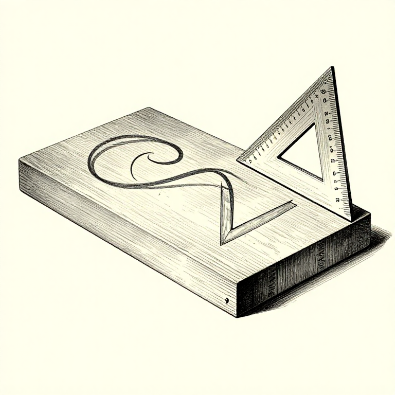


Face Side and Face Edge: Everything Is Measured From the Same Two Surfaces
Choose one face and one edge of every board, make them true, mark them, and measure everything from those two surfaces for the rest of the job. That is the whole idea, and it is the foundation the entire hand-tool series quietly assumes.
The reason is that errors do not add up if they all share an origin. Measure the second face from the first and it is parallel to it; measure it from the opposite face and it inherits whatever that face's error was. Work from one reference and mistakes stay put instead of compounding.
Zero published blueprints on Youblob covered this. It is the first thing a joiner is taught and the reason their work fits together.
Anfänger
2 hours
Anweisungen
1
1
Pick the best face, and make it true
Pick the best face, and make it true
Look at all four surfaces and choose the one that is flattest, has the best grain and is most likely to show. That becomes the FACE SIDE.
Make it flat — no twist, no cup, no bow. It does not have to be pretty, it has to be TRUE, because everything else in the job is going to be referenced from it. The next rung is how to test that honestly with winding sticks and a straightedge.
Choosing matters more than it sounds. A board with a knot where a joint will go, or with the best figure buried on the underside, is a decision you make once and live with. Spend the minute.
Materialien für diesen Schritt:
 Hartholzbrett1 Stück
Benötigte Werkzeuge:
 Haarlineal
 Handhobel
 Einschlaglupe
2
2
Then one edge, square to that face
Then one edge, square to that face
Choose an edge adjacent to the face side and plane it straight and SQUARE to that face — not square to anything else, and not merely straight.
Test with a try square held against the face side, sliding along the edge, sighted against the light. Any gap under the blade is out of square, and the eye can see a gap of a few hundredths this way. That becomes the FACE EDGE.
Now you have a reference corner: two true surfaces at a known right angle. Width is measured from the face edge, thickness from the face side, and every square line is struck with the square's stock against one of them.
Materialien für diesen Schritt:
Hartholzbrett1 StückBenötigte Werkzeuge:
 AnschlagwinkelHandhobel
 Schwerer Schraubstock
3
3
Mark them, and use the traditional marks
Mark them, and use the traditional marks
Draw a loose looping mark on the face side and an inverted V on the face edge, with the point of the V touching the face side's mark at the shared corner.
The marks do real work. They survive handling, they are unmistakable across a bench of similar boards, and because they meet at the corner they tell you which face goes with which edge — which matters once you have four boards that all look alike.
Put them where they will not be planed away, and where you can see them while working. Any consistent convention works; the traditional one has survived because it is quick to draw and impossible to confuse with a measuring mark.
Materialien für diesen Schritt:
Hartholzbrett2 StückBenötigte Werkzeuge:
Anschlagwinkel4
4
Always reference from the marks — never from the other side
Always reference from the marks — never from the other side
Every gauge, every square and every measurement registers against the face side or the face edge. The gauge's stock goes against the marked face, every time, on every board.
Do that and a small error in the board's thickness simply does not matter: the joint is cut at a fixed distance from a true surface, and the other surface can be whatever it likes. Reference from the wrong side once and that error lands directly in the joint.
This is also why a set of parts should be marked out together, from the same reference, in one session. Boards marked from different references fit their own measurements perfectly and each other not at all — which is the usual reason a carefully made assembly will not go together.
Materialien für diesen Schritt:
Hartholzbrett4 StückBenötigte Werkzeuge:
 StreichmaßAnschlagwinkel
Benötigte Werkzeuge
6- Platzhalter
- Platzhalter
- Platzhalter
- Platzhalter
- Platzhalter
- Platzhalter
Verwandte Blueprints
Diese Blueprints teilen Wissen — Techniken, Materialien oder Prinzipien


CC0 Gemeinfrei
Dieser Blueprint ist unter CC0 veröffentlicht. Sie dürfen dieses Werk für jeden Zweck frei kopieren, ändern, verbreiten und verwenden, ohne um Erlaubnis zu fragen.
Unterstützen Sie den Maker, indem Sie Produkte über seinen Blueprint kaufen, wo er eine Maker-Provision von Anbietern festgelegt, verdient. Oder erstellen Sie eine neue Iteration dieses Blueprints und verbinden Sie ihn in Ihrem eigenen Blueprint, um Einnahmen zu teilen.