Zusammenarbeit
KUNST
SCHÖNHEIT & WELLNESS
HANDWERK
KULTUR & GESCHICHTE
UNTERHALTUNG
UMFELD
ESSEN & GETRÄNKE
REVERSE ENGINEERING
WISSENSCHAFTEN
SPORT
TECHNOLOGIE
WEARABLES
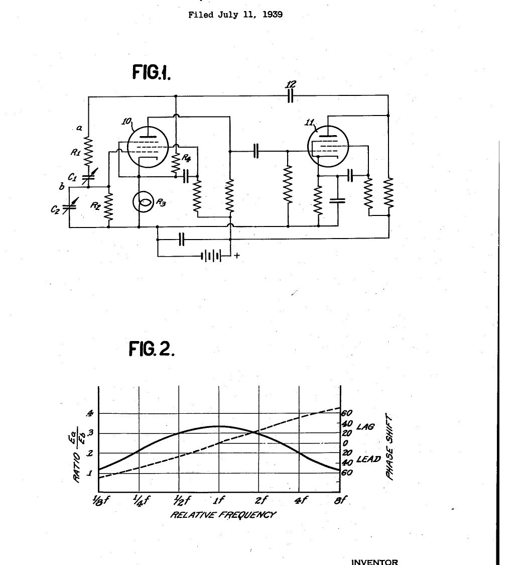


Function Generator: Resistance-Capacity Tuned Audio Oscillator with Lamp Amplitude Control (Hewlett, US 2,268,872, 1942)
The first Hewlett-Packard product: a test oscillator tuned by resistors and capacitors instead of coils. Two valve amplifiers feed their output back to their input through a series and a parallel R-C pair, which passes only one frequency in phase, so the circuit oscillates there. A second, negative feedback path through a small lamp holds the amplitude steady: as the swing grows the lamp warms, its resistance rises and the gain falls. One dial covers ten to one in frequency.
Result: a sine-wave signal generator covering 20 to 20,000 cycles in three ranges, about 0.25 % distortion.
Source: W. R. Hewlett, US 2,268,872 (1942). Unknown: valve types and component values. Picture: the patent drawing.
Erfahren
Unknown
Anweisungen
1
1
Build the two-stage amplifier
Build the two-stage amplifier
Wire two amplifying valves in cascade with resistance-capacity coupling, the first's anode to the second's grid, run as class A amplifiers. Not given: valve types, values, the supplies. Ours: pentode valves in sockets.
Materialien für diesen Schritt:
 Pentodenröhre2 Stück
 Röhrenfassung2 Stück
 Widerstand1 Set
 Kondensatorsortiment1 coupling and by-pass
 Aluminiumgehäuse1 case
 Lötdraht1 as needed
Benötigte Werkzeuge:
 Lötkolben
2
2
Fit the tuning network
Fit the tuning network
From the second valve's anode, through a coupling capacitor, feed back to the first valve's grid through a resistor R1 in series with a variable capacitor C1, with a resistor R2 and variable capacitor C2 from the grid to ground. Make R1 = R2 and C1 = C2: the frequency is then 1/(2 pi R C), set by the capacitors, giving 10 to 1 on one dial. For the capacitors use a four-gang tuning capacitor with its sections paired in parallel. Switch three sets of resistors in for the ranges 20-200, 200-2000 and 2000-20,000 cycles. Ours: a rotary switch.
Materialien für diesen Schritt:
 Drehkondensator (Luftdielektrikum)1 four-gangWiderstand1 three sets of R1, R2
 Drehschalter1 range switch
Benötigte Werkzeuge:
Lötkolben Schraubendreher-Satz
3
3
Fit the lamp feedback and use it
Fit the lamp feedback and use it
From the same output, through the coupling capacitor, feed back to the first valve's cathode across a resistor R4 and a small incandescent lamp R3. As the oscillation grows, the lamp heats, its resistance rises, the negative feedback increases and the gain falls, so the amplitude settles below the point of grid current with no clipping. The negative feedback also steadies the gain against valve and supply changes. Take the output from the terminals; Hewlett's test unit held its output within about 10 % over 20-20,000 cycles, with about 0.25 % distortion and under 0.1 % frequency shift with supply changes.
Materialien für diesen Schritt:
 Glühbirne1 small incandescent lampWiderstand1 R4
 Polklemme2 output
Benötigte Werkzeuge:
 GleichstromnetzgerätLötkolben
Materialien
10- 2 StückPlatzhalter
- 2 StückPlatzhalter
- 1 R4Platzhalter
- 1 coupling and by-passPlatzhalter
- 1 casePlatzhalter
- 1 as neededPlatzhalter
- 1 four-gangPlatzhalter
- 1 range switchPlatzhalter
- 1 small incandescent lampPlatzhalter
- Platzhalter
Dieser Bauplan stellt her

CC0 Gemeinfrei
Dieser Blueprint ist unter CC0 veröffentlicht. Sie dürfen dieses Werk für jeden Zweck frei kopieren, ändern, verbreiten und verwenden, ohne um Erlaubnis zu fragen.
Unterstützen Sie den Maker, indem Sie Produkte über seinen Blueprint kaufen, wo er eine Maker-Provision von Anbietern festgelegt, verdient. Oder erstellen Sie eine neue Iteration dieses Blueprints und verbinden Sie ihn in Ihrem eigenen Blueprint, um Einnahmen zu teilen.