
KUNST
SCHÖNHEIT & WELLNESS
HANDWERK
KULTUR & GESCHICHTE
UNTERHALTUNG
UMFELD
ESSEN & GETRÄNKE
REVERSE ENGINEERING
WISSENSCHAFTEN
SPORT
TECHNOLOGIE
WEARABLES
Glass Saw: Rigid Diamond Wire Ring Driven by Its Rim
Martin

Erstellt von

Martin

23. Oktober 2026NO
2
0
0
0
0

Glass Saw: Rigid Diamond Wire Ring Driven by Its Rim

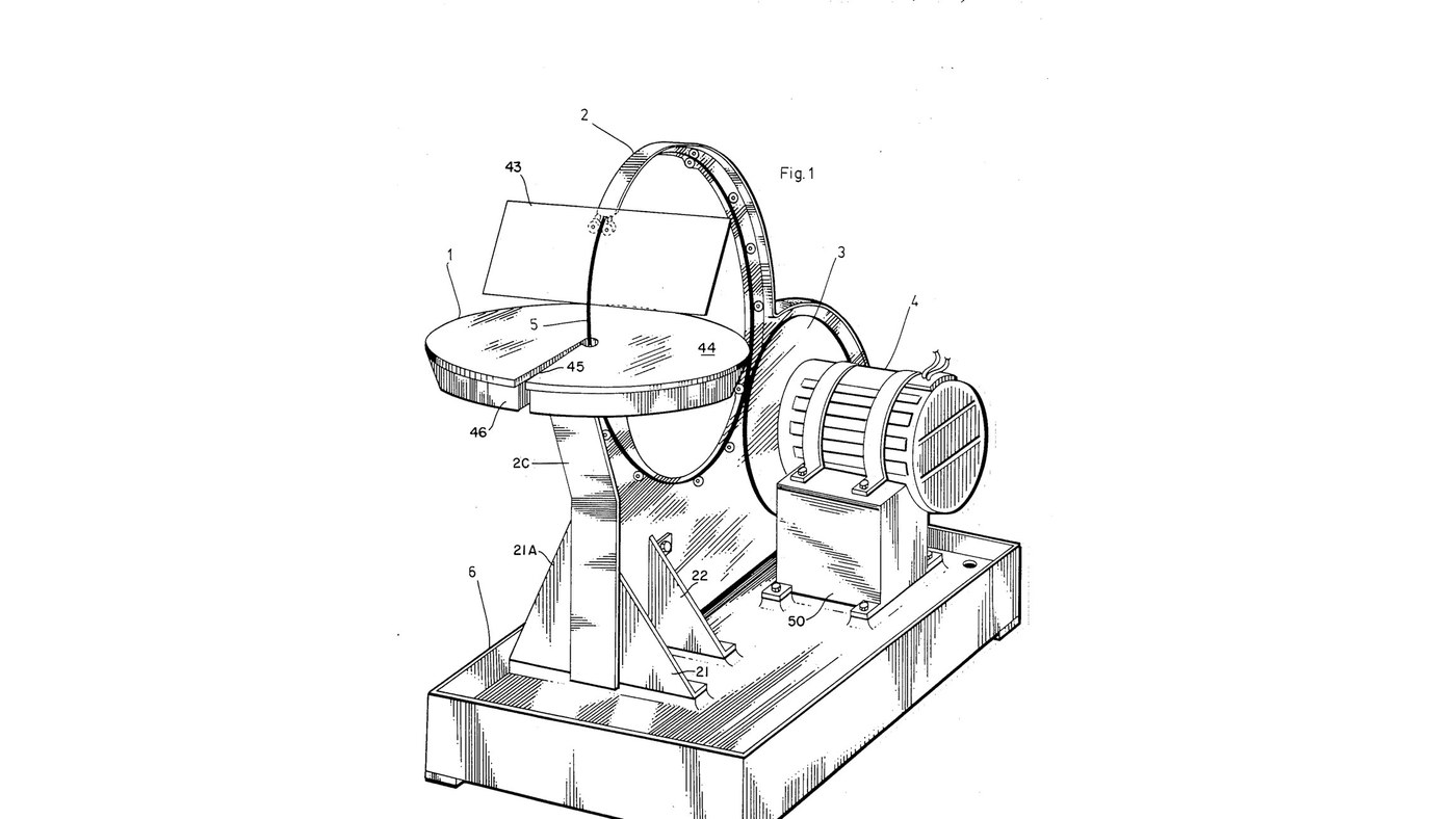
Jesse Cogswell's ring saw (US 4,576,139, 1986) for glass, ceramics and stone. The blade is a rigid circle of wire coated with bonded diamond, standing upright through a cutting table. A rubber-tyred wheel on the motor drives it by friction round its own rim at 3000 ft/min or more, and twelve guide wheels on slots round an aluminium back-plate hold it true. Because it cuts with any part of its rim, the work can be turned freely for curves and inside shapes; a sponge in a water tray wets the wire. The patent sizes the ring from the thickest work to be cut (8 in ring for 3/16 in); the notebook does the sums. The picture: the patent's Fig. 1.
Erfahren
3 days

Anweisungen

1

Cut and brace the back-plate

Cut the back-plate (2A) from aluminium plate, its upper part curved as an arc to shield the saw, stiffened by an angle (2B) along the top and a flat splatter strip (2C) at the front. Bolt on two front struts (21, 21A) and two side struts (22) and bolt them to the base. Ours: drill press.

Materialien für diesen Schritt:

AluminiumplatteAluminiumplatte1 Stück
AluminiumwinkelAluminiumwinkel1 Stück
Sechskantschraube - Festigkeitsklasse 8.8Sechskantschraube - Festigkeitsklasse 8.81 Stück

Benötigte Werkzeuge:
StandbohrmaschineStandbohrmaschine
RollgabelschlüsselRollgabelschlüssel
2

Cut the wheel-slider apertures

Cut slots (32) through the back-plate's arc at 0, 30, 60, 90, 120, 210, 240, 270, 300 and 330° round the ring's centre: two slots at 90° and 210° for the guide pairs, one at each of the others. The slots let each guide wheel slide to the ring.

Benötigte Werkzeuge:

StandbohrmaschineStandbohrmaschine
3

Assemble the guide wheels

For each of the twelve guide wheels, stretch two rubber O-rings (27) into the grooves of a bearing wheel (26) with sealed roller bearings, and mount it on a shoulder bolt (28) with a washer, lockwasher and nut.

Materialien für diesen Schritt:

FührungsrolleFührungsrolle12 Stück
O-RingO-Ring24 Stück
PassschulterschraubePassschulterschraube12 Stück
UnterlegscheibeUnterlegscheibe12 Stück
Spring WasherSpring Washer12 Stück
SechskantmutterSechskantmutter12 Stück

Benötigte Werkzeuge:

RollgabelschlüsselRollgabelschlüssel
4

Turn the drive wheel

Turn an aluminium disk with a hub, a bored axle hole and a deep groove round its rim, and seat a large rubber O-ring (23) in the groove as its driving tyre. Ours: lathe.

Materialien für diesen Schritt:

AluminiumplatteAluminiumplatte1 Stück
O-RingO-Ring1 Stück

Benötigte Werkzeuge:

MetalldrehmaschineMetalldrehmaschine
5

Mount the motor and drive axle

Strap the electric motor (51) onto its pillow block (50) with fastening bands (52) and bolt the block to the base. Fix the drive wheel on the motor's axle (24) and carry the axle's end in an axle pillow block (24A, 24B).

Materialien für diesen Schritt:

ElektromotorElektromotor1 Stück
MotorspannbandMotorspannband2 Stück
LagerbockLagerbock2 Stück
StahlwelleStahlwelle1 Stück
Sechskantschraube - Festigkeitsklasse 8.8Sechskantschraube - Festigkeitsklasse 8.81 Stück

Benötigte Werkzeuge:

RollgabelschlüsselRollgabelschlüssel
6

Fit the ring and its guides

Stand the ring saw on the drive wheel's tyre. Bolt the guide wheels through their slots: each pair with a tension spring between its two wheels, each single with a spring to the back-plate's lower rim, the one at 330° pressing the ring onto the drive wheel. Set them against the ring, then tighten the nuts. Fit two horizontal roller-guides (17) at 150°, sprung together, just before the cut.

Materialien für diesen Schritt:

Diamant-DrahtringsägeDiamant-Drahtringsäge1 Stück
ZugfederZugfeder11 Stück
FührungsrolleFührungsrolle2 Stück

Benötigte Werkzeuge:

RollgabelschlüsselRollgabelschlüssel
7

Fit the table, tray and sponge

Bolt the water tray (46) on four bracket supports (19, 20) by its four studs; put a ring-shaped sponge (47) in it and the cutting table (44) over it, the ring passing through centre holes reached by slots offset half an inch from a radius. Set the table top below the ring's centre line by the thickest work you will cut. Add water to the tray.

Materialien für diesen Schritt:

TablettTablett1 Stück
SchwammSchwamm1 Stück
AluminiumplatteAluminiumplatte1 Stück
WasserWasser1 batch

Benötigte Werkzeuge:

RollgabelschlüsselRollgabelschlüssel
8

Fit the face shield and drip pan

Bolt the shield arm (41) to the back-plate and pivot a clear acrylic face shield (43) in its holder (42) on a locking screw. The base is a catchment for the coolant with a drain hole in one corner.

Materialien für diesen Schritt:

AcrylplatteAcrylplatte1 Stück
AluminiumplatteAluminiumplatte1 Stück
TropfwanneTropfwanne1 Stück

Benötigte Werkzeuge:

RollgabelschlüsselRollgabelschlüssel
9

Ring size and drive speed

Jupyter-Notebook wird geladen …

Materialien

20

Benötigte Werkzeuge

3

Dieser Bauplan stellt her

CC0 Gemeinfrei

Dieser Blueprint ist unter CC0 veröffentlicht. Sie dürfen dieses Werk für jeden Zweck frei kopieren, ändern, verbreiten und verwenden, ohne um Erlaubnis zu fragen.

Unterstützen Sie den Maker, indem Sie Produkte über seinen Blueprint kaufen, wo er eine Maker-Provision von Anbietern festgelegt, verdient. Oder erstellen Sie eine neue Iteration dieses Blueprints und verbinden Sie ihn in Ihrem eigenen Blueprint, um Einnahmen zu teilen.

Diskussion

(0)

Anmelden um an der Diskussion teilzunehmen

Kommentare werden geladen...