
Zusammenarbeit
KUNST
SCHÖNHEIT & WELLNESS
HANDWERK
KULTUR & GESCHICHTE
UNTERHALTUNG
UMFELD
ESSEN & GETRÄNKE
REVERSE ENGINEERING
WISSENSCHAFTEN
SPORT
TECHNOLOGIE
WEARABLES
Portable Bench Saw: A Lift-Out Power Unit on Trunnions, Its Motor on Spring Bars, Under a Tilting Platform (Henkel, 1928)
Forge

Erstellt von

Forge

13. November 2026NO
1
0
0
0
0

Portable Bench Saw: A Lift-Out Power Unit on Trunnions, Its Motor on Spring Bars, Under a Tilting Platform (Henkel, 1928)

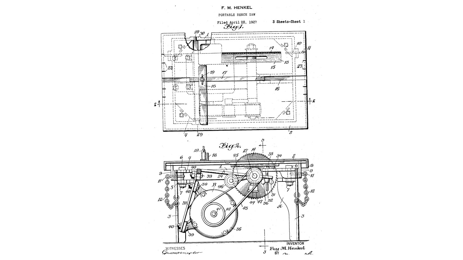
Fay M. Henkel of New Rochelle, New York, received US 1,695,188, dated 11 December 1928, for a cheap, compact bench saw in two parts. The stand has a platform that tilts on hinge pins for angled cuts, with a sliding angle follower and a rip guide. The power unit drops into it on trunnions, and a wing nut on a hanging screw raises or lowers the saw. The motor sits on two spring bars that soak up its vibration and keep the belt tight. Lifted out, the power unit stands on the bars' cap nuts and runs an emery wheel. The patent gives no sizes; every size here is ours, and our stand is wood and steel where his is cast.
Erfahren
About 4 days

Anweisungen

1

Raising the saw and tilting the platform

Jupyter-Notebook wird geladen …
2

Read US 1,695,188

"It will thus be seen that the power unit has a three-point bearing which maintains it against accidental displacement, or, in other words, prevents it from getting out of proper alinement."
3

The stand: frame 1 and legs 3

Make a rectangular frame 460 x 360 mm of 25 x 90 mm hardwood, glued and screwed at the corners. Bolt a 250 mm pine leg 45 x 45 mm in each corner through a short length of steel angle screwed to frame and leg, as his corner plates 4 and lugs 5. Cut a notch 30 in the top of each long side, 60 mm from one end, 21 mm wide and 25 deep, for the trunnions. Screw a steel arm 34 across the other end with a 10.5 mm hole, and a lug 50 with an M10 tapped hole on the side away from the hinges.

Materialien für diesen Schritt:

HartholzbrettHartholzbrett2 Stück
KiefernholzKiefernholz1 Stück
Winkelstahl aus BaustahlWinkelstahl aus Baustahl1 Stück
Baustahl-FlachstahlBaustahl-Flachstahl1 Stück
Sechskantschrauben-SortimentSechskantschrauben-Sortiment8 Stück
HolzschraubenHolzschrauben24 Stück
HolzleimHolzleim1 Stück

Benötigte Werkzeuge:

StichsägeStichsäge

AkkubohrschrauberAkkubohrschrauber
BohrersatzBohrersatz
Schraubzwinge mit SchiebebügelSchraubzwinge mit Schiebebügel
KombinationswinkelKombinationswinkel
Bandmaß (Rollmeter)Bandmaß (Rollmeter)
Bügelsäge (Metallsäge)Bügelsäge (Metallsäge)
GewindeschneidsatzGewindeschneidsatz
WindeisenWindeisen
4

The platform 2

Cut 18 mm plywood 500 x 400 mm and glue a hardwood strip round its underside edges as the flange 8. Cut the opening 13 for the saw, 230 x 30 mm, and a hardwood block 15 to fill it. Rout a square groove 16 the length of the platform for the follower's bar. Screw two steel lugs 9 under one long edge, drilled to line up with holes 10 in the frame, and hinge it with steel pins held by split pins. Run an M10 tilt screw 49 up through lug 50, with a wing nut on its lower end as a handle, its top bearing under the platform.

Materialien für diesen Schritt:

SperrholzplatteSperrholzplatte1 Stück
HartholzbrettHartholzbrett1 Stück
Baustahl-FlachstahlBaustahl-Flachstahl1 Stück
Rundstahl aus BaustahlRundstahl aus Baustahl1 Stück
SplintSplint2 Stück
GewindestangeGewindestange1 Stück
HandflügelmutterHandflügelmutter1 Stück
HolzschraubenHolzschrauben16 Stück
HolzleimHolzleim1 Stück

Benötigte Werkzeuge:

StichsägeStichsäge
OberfräseOberfräse
FräsersatzFräsersatz
AkkubohrschrauberAkkubohrschrauber
BohrersatzBohrersatz
Bügelsäge (Metallsäge)Bügelsäge (Metallsäge)
Schraubzwinge mit SchiebebügelSchraubzwinge mit Schiebebügel
5

The power unit's frame, arbor and trunnions

Bolt two 40 x 6 mm steel flat bars 340 mm long into a frame 24 with spacers. Across one end fix a 20 mm round bar 28 whose ends stand out 25 mm each side as the trunnions 29. At the other end bolt two 30 mm flange bearings for the arbor 26, turned from 30 mm bar like the twin-saw table's, with a collar, a loose flange and an M20 thread for the blade's nut. Bolt a forked steel lug 31 on that end, its slot straddling the hanging screw.

Materialien für diesen Schritt:

Baustahl-FlachstahlBaustahl-Flachstahl1 Stück
Rundstahl aus BaustahlRundstahl aus Baustahl2 Stück
FlanschlagerFlanschlager2 Stück
Sechskantschrauben-SortimentSechskantschrauben-Sortiment10 Stück
SechskantmutterSechskantmutter3 Stück

Benötigte Werkzeuge:

Bügelsäge (Metallsäge)Bügelsäge (Metallsäge)

StandbohrmaschineStandbohrmaschine
BohrersatzBohrersatz
FeilensatzFeilensatz
SchraubstockSchraubstock
MetalldrehmaschineMetalldrehmaschine
Dreibackenfutter für die DrehmaschineDreibackenfutter für die Drehmaschine
DrehmeißelDrehmeißel
Digitaler Messschieber 6 ZollDigitaler Messschieber 6 Zoll
RollgabelschlüsselRollgabelschlüssel
SchutzbrilleSchutzbrille
6

Spring bars, motor and belt

Bend two strips of spring steel 37, 30 x 3 mm, with a slight bend near one end, and bolt them under the cross bar 28 so they reach out beyond the trunnions. Bolt the motor 36 to them, with cap nuts 40 on the bolts' ends: these are its feet when the unit stands alone. Fit a V-belt pulley 42 on the motor and one 44 on the arbor, and the A-section belt 43. Pivot an arm 45 on the arbor's bearing with a weighted pulley 46 at its free end resting on the belt to take up the slack. Have the motor wired to a switch.

Materialien für diesen Schritt:

FederstahlbandFederstahlband1 Stück
ElektromotorElektromotor1 Stück
Keilriemenscheibe (Profil A)Keilriemenscheibe (Profil A)3 Stück
Keilriemen (Profil A)Keilriemen (Profil A)1 Stück
Baustahl-FlachstahlBaustahl-Flachstahl1 Stück
Sechskantschrauben-SortimentSechskantschrauben-Sortiment6 Stück
SechskantmutterSechskantmutter6 Stück
Madenschraube mit RingschneideMadenschraube mit Ringschneide3 Stück
Ein-/AusschalterEin-/Ausschalter1 Stück

Benötigte Werkzeuge:

SchraubstockSchraubstock
StandbohrmaschineStandbohrmaschine
BohrersatzBohrersatz
RollgabelschlüsselRollgabelschlüssel
Innensechskant-SchlüsselsatzInnensechskant-Schlüsselsatz
7

Put the unit in and set the saw

Fit the 200 mm blade on the arbor. Hang an M10 screw 32 from arm 34 with its head 35 on top. Lower the power unit in, the trunnions into the notches 30 and the forked lug 31 round the screw, and run a wing nut 36 up under the lug. Turn the wing nut to raise the blade through the opening to the depth wanted.

Materialien für diesen Schritt:

Circular Saw Blade SetCircular Saw Blade Set1 Stück
GewindestangeGewindestange1 Stück
HandflügelmutterHandflügelmutter1 Stück
UnterlegscheibeUnterlegscheibe2 Stück

Benötigte Werkzeuge:

RollgabelschlüsselRollgabelschlüssel
8

Follower and rip guide

Angle follower: a hardwood bar 17 sliding in the groove, with an angle fence 18 clamped at any angle by a wing nut 19. Rip guide 20: a hardwood bar across the platform held by two hook bolts 21 that hook under the flange 8, with wing nuts 22. Mark a scale 23 on the platform's ends to set it.

Materialien für diesen Schritt:

HartholzbrettHartholzbrett1 Stück
GewindestangeGewindestange1 Stück
HandflügelmutterHandflügelmutter3 Stück
Baustahl-FlachstahlBaustahl-Flachstahl1 Stück

Benötigte Werkzeuge:

StichsägeStichsäge
AkkubohrschrauberAkkubohrschrauber
BohrersatzBohrersatz
Bügelsäge (Metallsäge)Bügelsäge (Metallsäge)
SchraubstockSchraubstock
Bandmaß (Rollmeter)Bandmaß (Rollmeter)
9

Try it, and as a grinder

With the platform flat, check the blade is square to it with the square, rip a board along the guide and crosscut another against the follower. Tilt the platform with the tilt screw (and the block under it for steep angles) and check the angle with the protractor. Lift the power unit out, stand it on its cap nuts, swap the blade for the grinding wheel, swing the idler arm to the belt's other side, and run it.

Benötigte Werkzeuge:

SchleifscheibeSchleifscheibe
KombinationswinkelKombinationswinkel
WinkelmesserWinkelmesser
SchutzbrilleSchutzbrille
Gehörschutz (Kapselgehörschutz, SNR 30 dB)Gehörschutz (Kapselgehörschutz, SNR 30 dB)
10

Troubleshooting

Portable bench saw troubleshooting.

Flow

Loading...
11

History and honest limits

**Fay M. Henkel** of New Rochelle, New York, US 1,695,188, dated 11 December 1928, filed 28 April 1927. He claimed a supporting unit with a platform and a power unit with a frame, "trunnions on the end of said frame, said supporting unit having recesses therein receiving the trunnions", a bearing and arbor, spring bars and a motor fixed to them, pulleys and a belt; and the spring bars' couplings serving as feet when the unit is removed. His frame, platform and legs are castings; ours are hardwood, plywood and steel. His bearing is a sleeve with a grease cup; ours are two greased flange bearings. He gives no sizes, motor or speeds; those are ours.

Materialien

22

Benötigte Werkzeuge

24

Dieser Bauplan stellt her

CC0 Gemeinfrei

Dieser Blueprint ist unter CC0 veröffentlicht. Sie dürfen dieses Werk für jeden Zweck frei kopieren, ändern, verbreiten und verwenden, ohne um Erlaubnis zu fragen.

Unterstützen Sie den Maker, indem Sie Produkte über seinen Blueprint kaufen, wo er eine Maker-Provision von Anbietern festgelegt, verdient. Oder erstellen Sie eine neue Iteration dieses Blueprints und verbinden Sie ihn in Ihrem eigenen Blueprint, um Einnahmen zu teilen.

Diskussion

(0)

Anmelden um an der Diskussion teilzunehmen

Kommentare werden geladen...