KUNST
SCHÖNHEIT & WELLNESS
HANDWERK
KULTUR & GESCHICHTE
UNTERHALTUNG
UMFELD
ESSEN & GETRÄNKE
REVERSE ENGINEERING
WISSENSCHAFTEN
SPORT
TECHNOLOGIE
WEARABLES
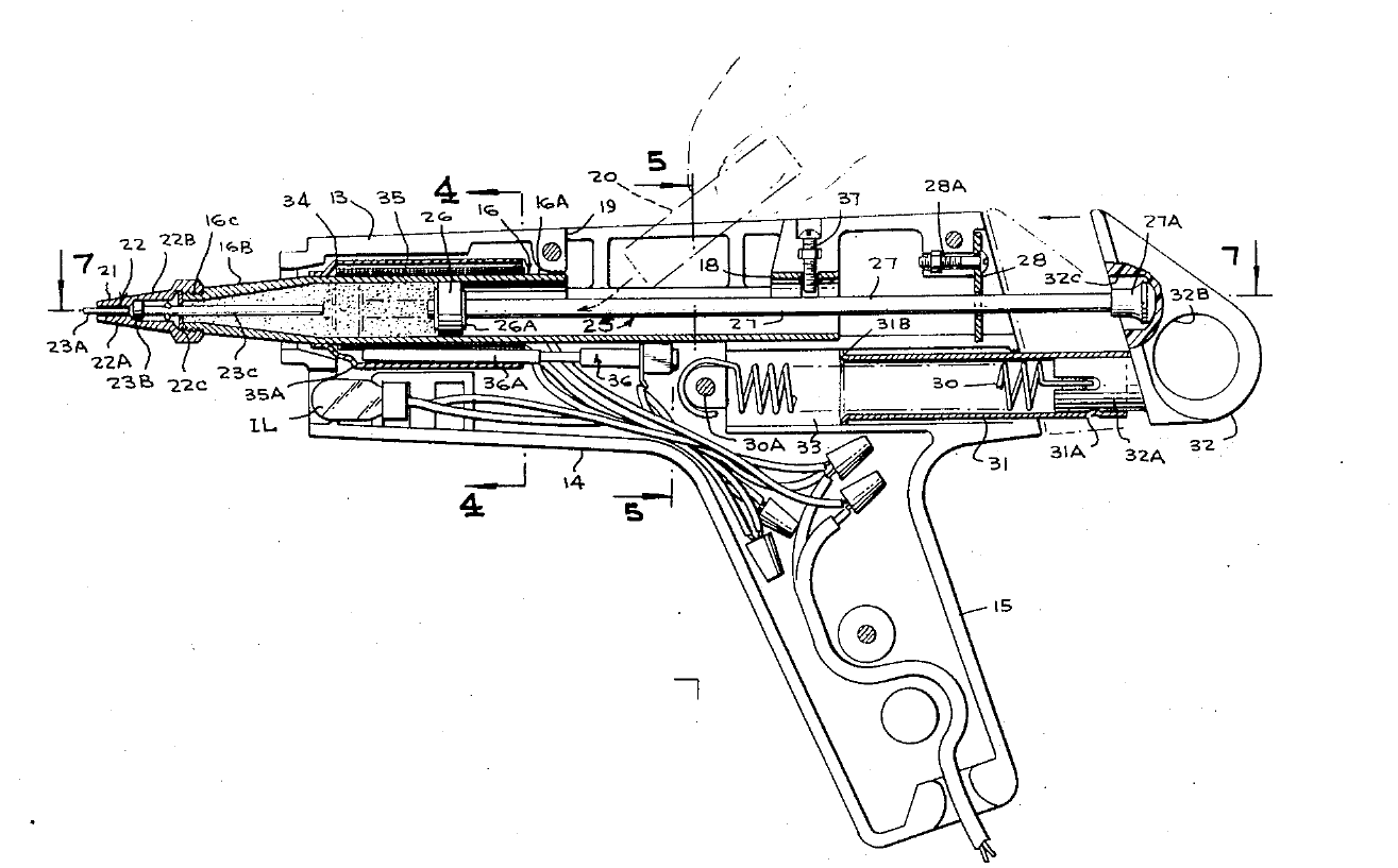


Hot Glue Gun: Weller & Brassaw, 1973
Carl E. Weller and Alden J. Brassaw, for Cooper Industries, patented this glue gun in 1973, US 3,744,921. A stick of solid hot-melt adhesive drops through a loading well into a tubular melt chamber that narrows to a nozzle. Mica sheet wound with nichrome wire and closed by a metal sleeve heats the chamber, under a thermostat. Instead of a thumb, ratchet or feed wheel pushing the stick, a spring drives a Teflon-tipped piston forward against it. A valve pin in the nozzle keeps it closed against dripping; pressing the projecting pin on the work opens it and the glue flows.
Erfahren
Factory process
Anweisungen
1
1
Housing and melt chamber
Housing and melt chamber
Fit the elongated tubular melt chamber between the two pistol-shaped housing halves: a uniform cylindrical barrel with a loading well opening through the top of the housing, a converging conical forward part and a threaded end.
Materialien für diesen Schritt:
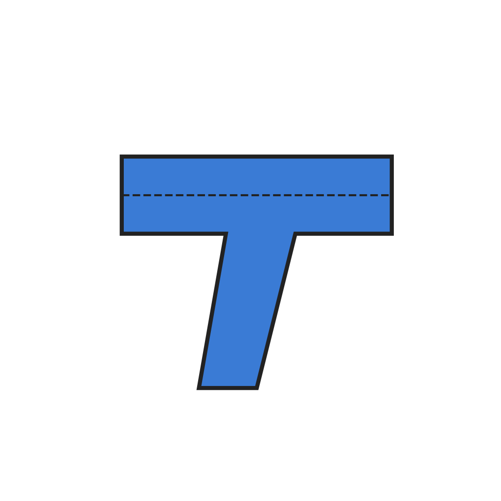 Heißklebepistolen-Gehäusehälften1 Stück
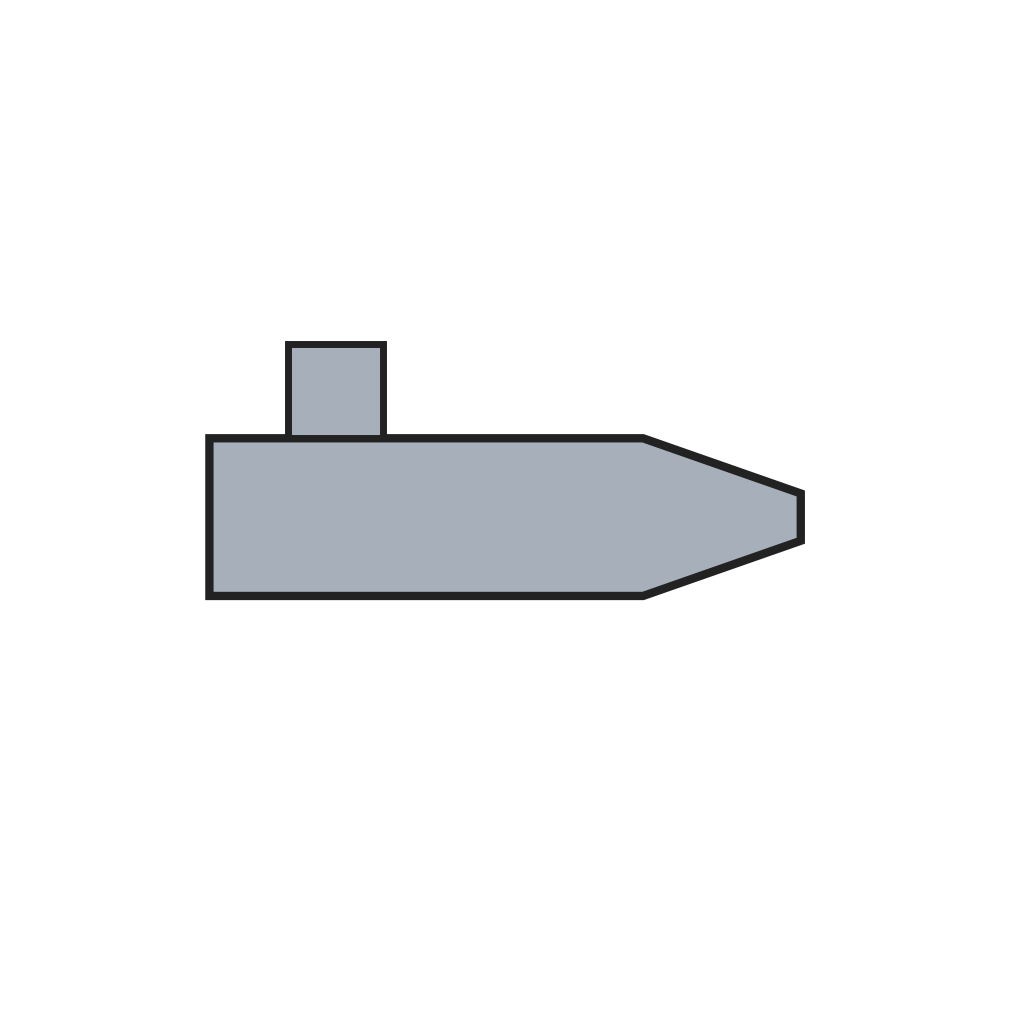 Rohrförmige Schmelzkammer1 Stück
Benötigte Werkzeuge:
 Schraubendreher-Satz
2
2
Heater
Heater
Wrap mica sheeting spirally round the barrel with nichrome windings between the layers, close it in a tubular metal sleeve, and fit the thermostat in its well against it.
Materialien für diesen Schritt:
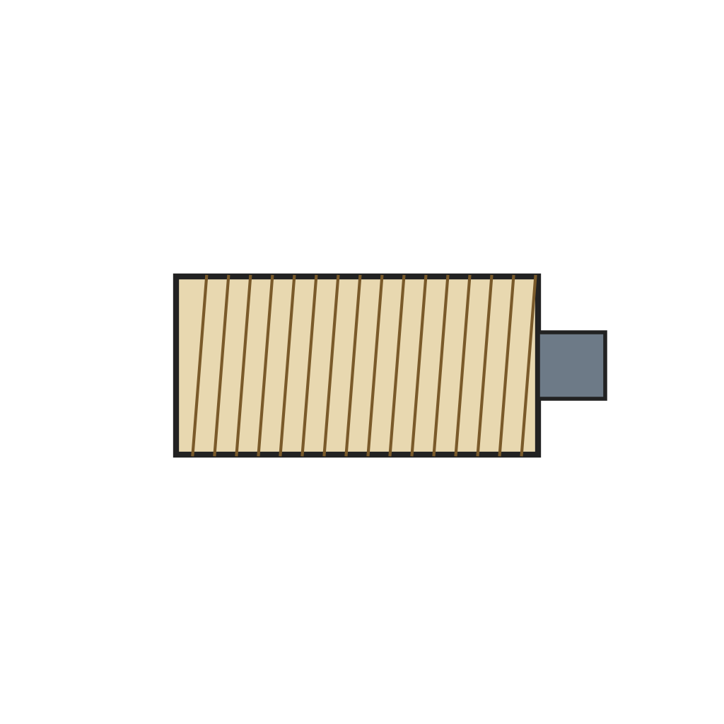 Glimmergewickelter Nichrom-Heizer mit Thermostat1 Stück
 Nichromdraht1 as required
 Glimmerplatte1 as required
Benötigte Werkzeuge:
 Kombizange
3
3
Nozzle and valve
Nozzle and valve
Screw the nozzle onto the threaded end. Inside it, the valve pin's enlarged portion seats against the bore's step and its tip projects from the outlet; glue pressure holds it shut until the tip is pressed against the work.
Materialien für diesen Schritt:
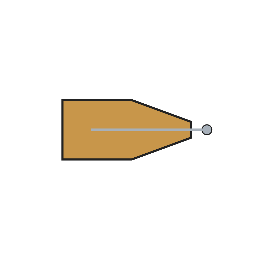 Klebedüse mit Ventil1 Stück
Benötigte Werkzeuge:
 Rollgabelschlüssel
4
4
Plunger
Plunger
Fit the plunger, a Teflon piston on a rod guided by a plate, behind the loading well, with its knob outside the housing; couple it to the spring in its tube through the pull device so the spring pushes the glue stick forward.
Materialien für diesen Schritt:
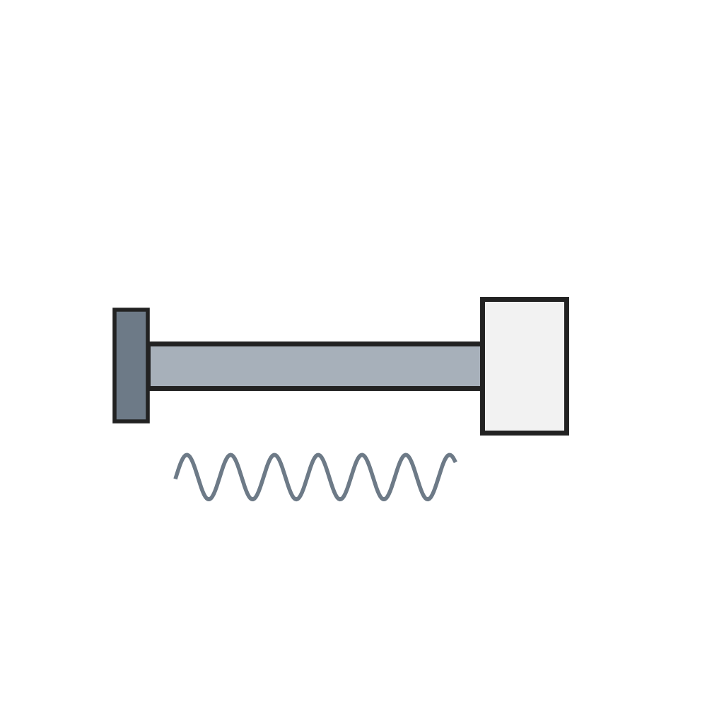 Federbelasteter Stößel mit Teflon-Kolben1 Stück
Benötigte Werkzeuge:
Schraubendreher-SatzMaterialien
7- Platzhalter
- 1 StückPlatzhalter
- Platzhalter
- 1 as requiredPlatzhalter
- 1 as requiredPlatzhalter
- 1 StückPlatzhalter
- Platzhalter
Benötigte Werkzeuge
3- Platzhalter
- Platzhalter
- Platzhalter
Dieser Bauplan stellt her
Verwandte Blueprints
Diese Blueprints teilen Wissen — Techniken, Materialien oder Prinzipien
CC0 Gemeinfrei
Dieser Blueprint ist unter CC0 veröffentlicht. Sie dürfen dieses Werk für jeden Zweck frei kopieren, ändern, verbreiten und verwenden, ohne um Erlaubnis zu fragen.
Unterstützen Sie den Maker, indem Sie Produkte über seinen Blueprint kaufen, wo er eine Maker-Provision von Anbietern festgelegt, verdient. Oder erstellen Sie eine neue Iteration dieses Blueprints und verbinden Sie ihn in Ihrem eigenen Blueprint, um Einnahmen zu teilen.