Zusammenarbeit
KUNST
SCHÖNHEIT & WELLNESS
HANDWERK
KULTUR & GESCHICHTE
UNTERHALTUNG
UMFELD
ESSEN & GETRÄNKE
REVERSE ENGINEERING
WISSENSCHAFTEN
SPORT
TECHNOLOGIE
WEARABLES
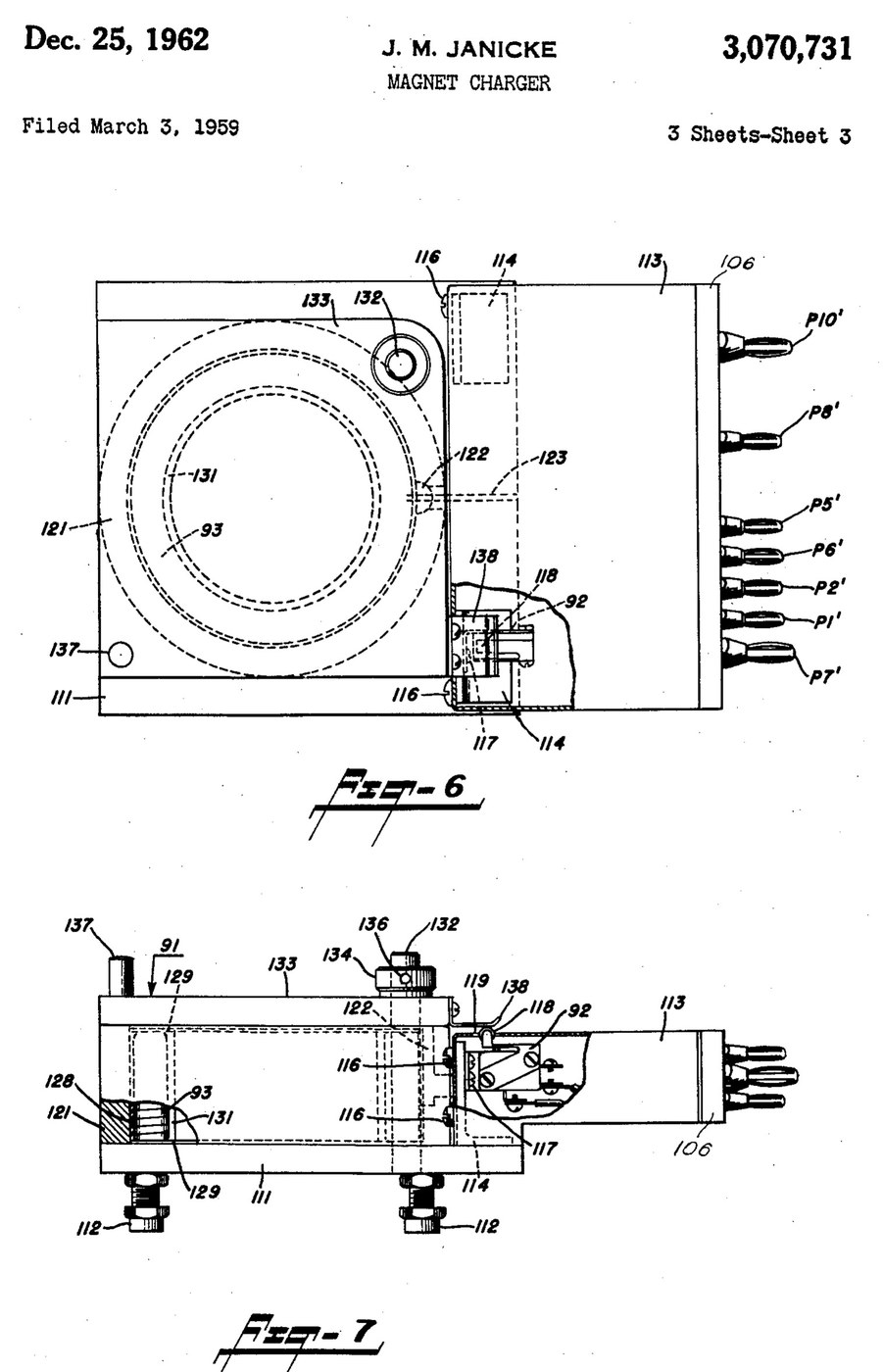


Magnetiser: Capacitor-Discharge Magnet Charger with a Wire-Wound Fixture (Janicke, US 3,070,731, 1962)
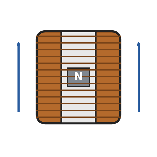
An impulse magnetiser. A capacitor is charged to a high voltage, then an ignitron dumps it all at once through a coil. The magnet sits inside the coil in a closed steel pot, so almost all of the flux goes through it.
Result: a magnet charger that magnetises rods, bars and blocks in one pulse, with an interlocked lid.
Source: J. M. Janicke, US 3,070,731 (1962). Unknown: voltages, capacitance, coil windings, field strength and sizes. Picture: the patent drawing.
Experte
Unknown
Anweisungen
1
1
Build the charging supply
Build the charging supply
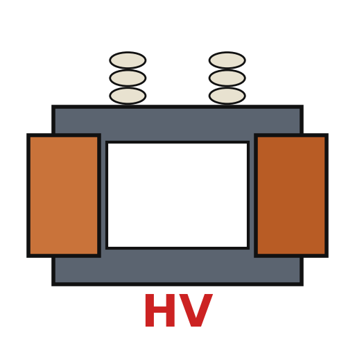
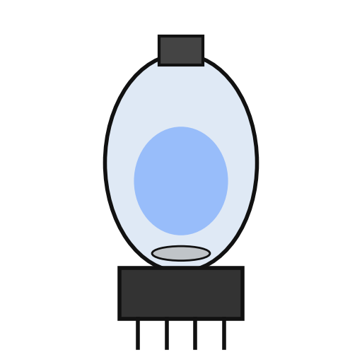
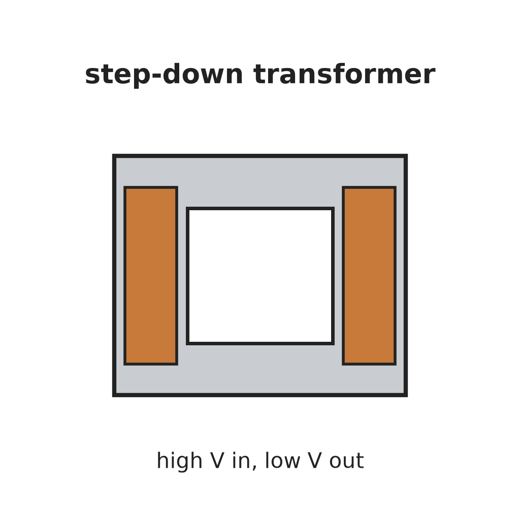
Feed a line switch from the mains through two fuses, with a pilot lamp. Wire a high-voltage transformer with two primaries, which a high-low switch puts in series or in parallel. Run its centre-tapped secondary to two mercury-vapour rectifier tubes, "or the like", with their own filament transformer, so they charge the energy-storage capacitor. A charging on-off switch with a red lamp switches the high-voltage side. A meter with multiplier resistors across the capacitor shows its voltage. Ours: toggle switches, neon lamps, a moving-coil meter. Not given: any voltage or value.
Materialien für diesen Schritt:
 Hochspannungstransformator1 high-voltage transformer
 Quecksilberdampf-Gleichrichterröhre2 rectifier tubes
 Abwärtstransformator1 filament transformer
 Energiespeicherkondensator1 storage capacitor
 Drehspul-Einbaumessgerät1 voltage meter
 Unbekannter Widerstand2 meter multipliers
 Kippschalter3 line, charging and high-low switches
 Schmelzsicherung2 fuses
 Neon-Glimmlampe2 pilot and red lamps
Benötigte Werkzeuge:
 Lötkolben
 Abisolierzange
2
2
Add the delay and the bleeder
Add the delay and the bleeder
Put a thermal time-delay relay before the charging switch: about thirty seconds after switch-on it energises a control relay, which feeds the charging switch and holds itself on. A third contact of the control relay lifts a bleeder resistor off the capacitor while the charger runs. When the charger is shut down the relay drops out and the bleeder drains the dangerous high-voltage charge from the capacitor.
Materialien für diesen Schritt:
 Zeitrelais1 thermal delay relay
 Relais1 control relay, three contact setsUnbekannter Widerstand1 bleeder resistor
Benötigte Werkzeuge:
LötkolbenAbisolierzange3
3
Fit the ignitron firing circuit
Fit the ignitron firing circuit
Put an ignitron in the discharge path of the storage capacitor, as its switch. The meter's multiplier resistors also form a divider that charges a small firing capacitor. Pressing the push button discharges the firing capacitor through a small limiting resistor into the ignitron's igniter, and the ignitron conducts. Not given: the firing capacitor's type and value.
Materialien für diesen Schritt:
 Ignitron1 discharge switch
 Unbekanntes Material1 firing capacitorUnbekannter Widerstand1 limiting resistor
 Drucktaster1 charge button
Benötigte Werkzeuge:
LötkolbenAbisolierzange4
4
Build the wire-wound fixture
Build the wire-wound fixture
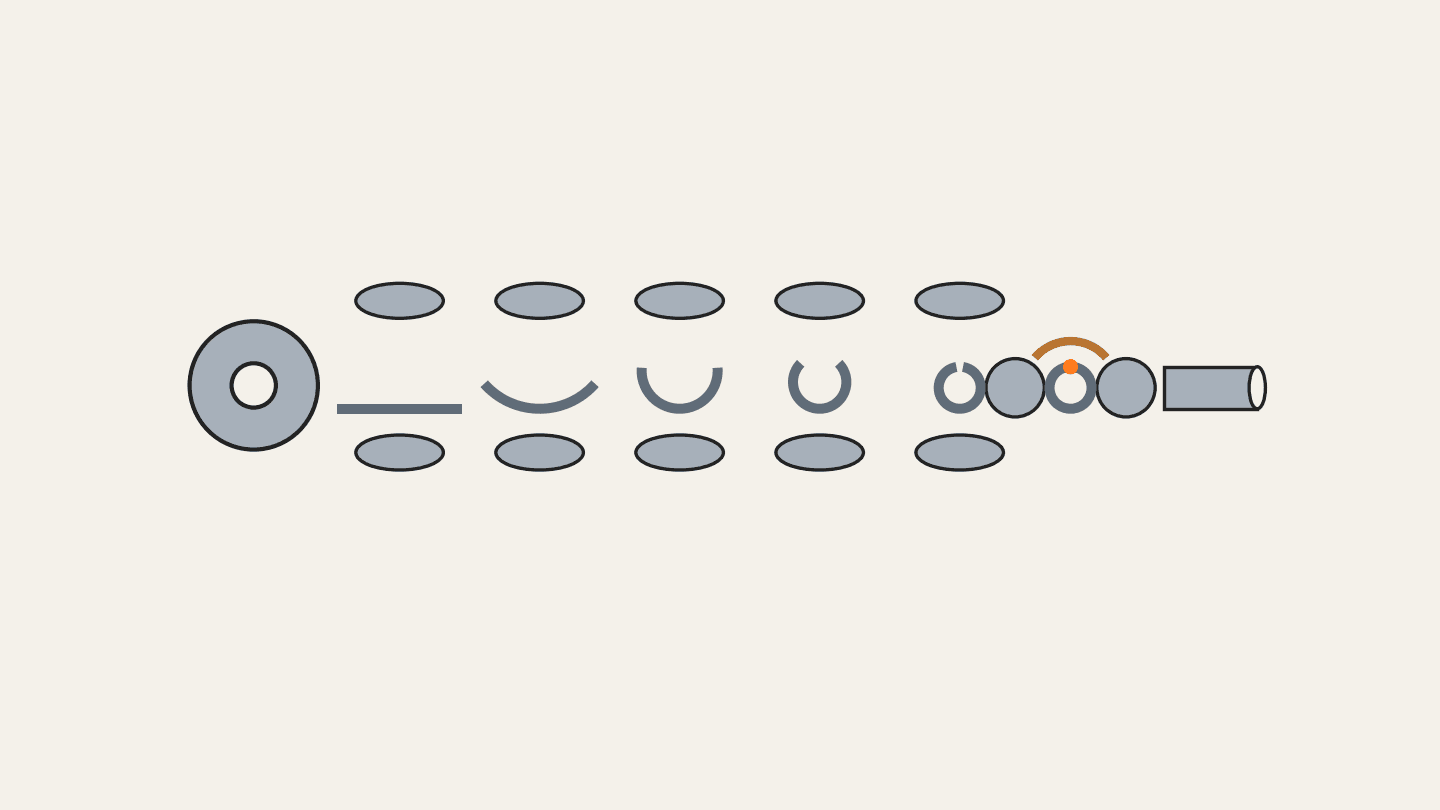
Weld a hollow cylindrical shell onto a base plate on levelling legs, both of magnetic material, to make a pot. Cut slots through the shell and the base plate so they cannot act as a shorted single-turn winding. Set the coil inside the shell in potting compound, with ring-shaped end pieces and a hollow cylindrical core in it. Hinge a square magnetic cover on a post beside the shell, held by a collar and set screw, with a handle. An L-shaped plate on the cover closes a switch in the igniter circuit only when the cover is shut. Wire the coil between the storage capacitor and the ignitron anode. Ours: mild steel, enamelled copper wire, casting epoxy. Not given: sizes, turns.
Materialien für diesen Schritt:
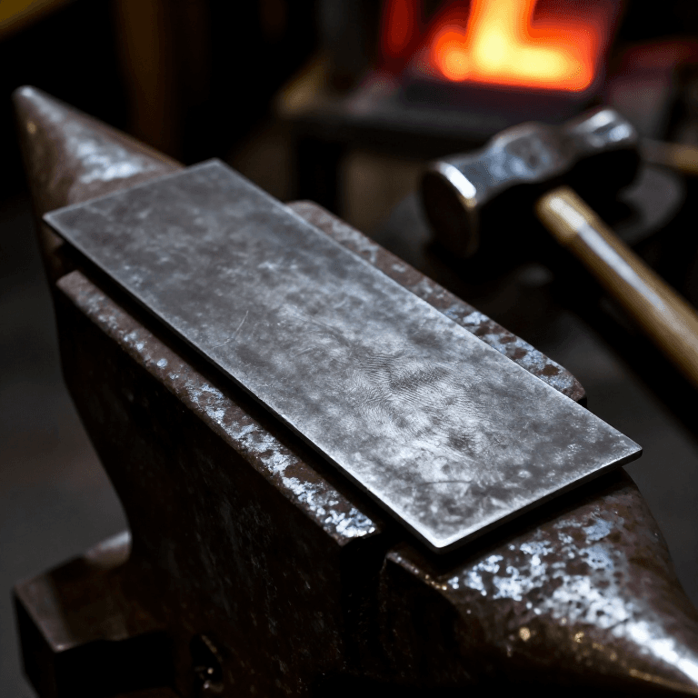
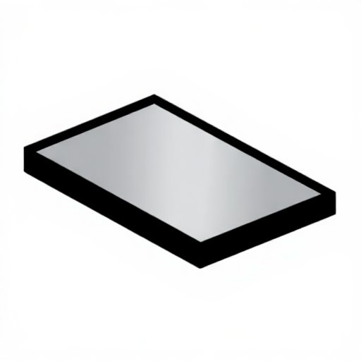 Baustahlplatte1 base plate and cover
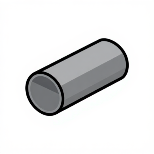 Rundrohr aus Flussstahl1 shell
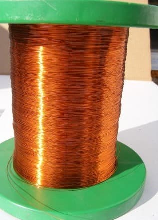
 Lackierter Kupferdraht1 coil
 Schwarzes Gießharz1 potting compound
 Unbekanntes Metall1 end pieces, core, post, legs
 Mikroschalter (mit Hebel)1 lid interlock switch
Benötigte Werkzeuge:
 Lichtbogen-Schweißgerät
 Standbohrmaschine
 Schraubendreher-Satz
 Unbekannte Maße
5
5
Charge a magnet
Charge a magnet
Put the magnet inside the core. Fill most of the air gap between it and the base plate and cover with soft iron, but leave a small gap near the cover, or the cover will be hard to swing open afterwards. Lay insulating material about 1/16 inch thick on top of the magnet. Close the cover, which arms the igniter switch, charge the capacitor, and press the button: one pulse magnetises it. Ours: wrought iron for the soft iron.
Benötigte Werkzeuge:
 Schmiedeeisenstange
 Unbekannter Isolierstoff
Materialien
20- 1 high-voltage transformerPlatzhalter
- 2 rectifier tubesPlatzhalter
- 1 filament transformerPlatzhalter
- 1 storage capacitorPlatzhalter
- 1 voltage meterPlatzhalter
- 1 limiting resistorPlatzhalter
- Platzhalter
- 2 fusesPlatzhalter
- 2 pilot and red lampsPlatzhalter
- 1 thermal delay relayPlatzhalter
- 1 control relay, three contact setsPlatzhalter
- 1 discharge switchPlatzhalter
- 1 firing capacitorPlatzhalter
- Platzhalter
- 1 base plate and coverPlatzhalter
- 1 shellPlatzhalter
- 1 coilPlatzhalter
- 1 potting compoundPlatzhalter
- 1 end pieces, core, post, legsPlatzhalter
- 1 lid interlock switchPlatzhalter
Benötigte Werkzeuge
8- 2 vendors sell this, none ship to you yetPlatzhalter
- Platzhalter
- Platzhalter
- Platzhalter
- Platzhalter
- Platzhalter
- Platzhalter
- Platzhalter
Materialien verbundener Blueprints


Dieser Bauplan stellt her
CC0 Gemeinfrei
Dieser Blueprint ist unter CC0 veröffentlicht. Sie dürfen dieses Werk für jeden Zweck frei kopieren, ändern, verbreiten und verwenden, ohne um Erlaubnis zu fragen.
Unterstützen Sie den Maker, indem Sie Produkte über seinen Blueprint kaufen, wo er eine Maker-Provision von Anbietern festgelegt, verdient. Oder erstellen Sie eine neue Iteration dieses Blueprints und verbinden Sie ihn in Ihrem eigenen Blueprint, um Einnahmen zu teilen.