
KUNST
SCHÖNHEIT & WELLNESS
HANDWERK
KULTUR & GESCHICHTE
UNTERHALTUNG
UMFELD
ESSEN & GETRÄNKE
REVERSE ENGINEERING
WISSENSCHAFTEN
SPORT
TECHNOLOGIE
WEARABLES
Metal Band Saw: Horizontal Saw on a Welded Steel Frame
Martin

Erstellt von

Martin

23. Oktober 2026NO
2
0
0
0
0

Metal Band Saw: Horizontal Saw on a Welded Steel Frame

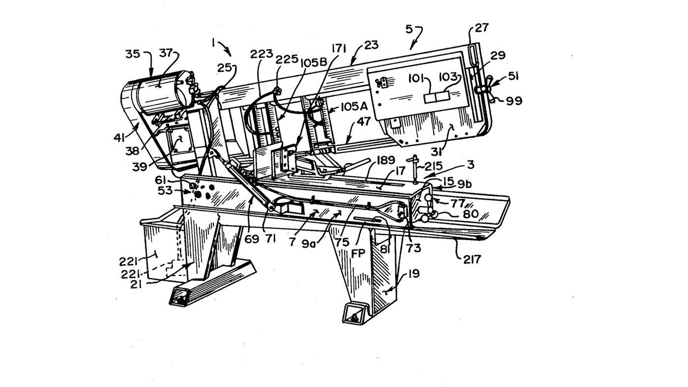
Curtis Eccardt's horizontal power band saw (Emerson Electric, US 4,364,294, 1982), built from welded steel channel and tube instead of iron castings to cut its cost. The saw head swings down on trunnions over the bed; a hydraulic cylinder with a valve sets how fast it feeds, a spring counterbalances it, and a spring tensioner shows the blade tension on a scale. Two guides with rollers twist the blade's lower run 90° so its teeth face down into the work, and carbide inserts hold it there. The patent gives no sizes, speeds or ratings; the welder and wrenches are ours. The picture: the patent's Fig. 1.
Erfahren
4 days

Anweisungen

1

Weld the bed

Stand two steel channels (9a, 9b) parallel, webs upright and flanges facing in, and weld gussets (15) between their webs. Bolt a bed plate (17) across the top flanges as the work surface. Ours: MIG welder, drill press for the bolt holes.

Materialien für diesen Schritt:

Stahl-U-ProfilStahl-U-Profil2 Stück
BaustahlplatteBaustahlplatte1 Stück
Sechskantschraube - Festigkeitsklasse 8.8Sechskantschraube - Festigkeitsklasse 8.81 Stück

Benötigte Werkzeuge:

MIG-SchweißgerätMIG-Schweißgerät
StandbohrmaschineStandbohrmaschine
RollgabelschlüsselRollgabelschlüssel
2

Weld and bolt on the legs

Weld formed sheet-steel legs onto horizontal floor members to make front and rear leg weldments (19, 21), and bolt them under the bed.

Materialien für diesen Schritt:

StahlblechStahlblech1 Stück
Stahlrohr (Konstruktionsrohr)Stahlrohr (Konstruktionsrohr)1 Stück
Sechskantschraube - Festigkeitsklasse 8.8Sechskantschraube - Festigkeitsklasse 8.81 Stück

Benötigte Werkzeuge:

MIG-SchweißgerätMIG-Schweißgerät
RollgabelschlüsselRollgabelschlüssel
3

Weld the head

Weld a head post (25) of square or rectangular steel tube square to a head beam (27) of rectangular tube. Weld a bracket leg (29) down from the beam's outer end, and fix support plates at both ends (31, 33).

Materialien für diesen Schritt:

Stahlrohr (Konstruktionsrohr)Stahlrohr (Konstruktionsrohr)1 Stück
BaustahlplatteBaustahlplatte1 Stück

Benötigte Werkzeuge:

MIG-SchweißgerätMIG-Schweißgerät
4

Fit the trunnions and align the pivot

Fix a shaft through the head post with its ends out as trunnions (55a, 55b), in bushings in two bearing blocks (59a, 59b) bolted inside the channel webs. Each block has one close-fit bolt hole and three oversize ones: shift the blocks until the pivot is parallel to the bed plate, then torque the bolts. A set screw (67) takes out end play.

Materialien für diesen Schritt:

StahlwelleStahlwelle1 Stück
MetallbuchseMetallbuchse2 Stück
LagerbockLagerbock2 Stück
Sechskantschraube - Festigkeitsklasse 8.8Sechskantschraube - Festigkeitsklasse 8.88 Stück
Madenschraube mit RingschneideMadenschraube mit Ringschneide1 Stück

Benötigte Werkzeuge:

StandbohrmaschineStandbohrmaschine
DrehmomentschlüsselDrehmomentschlüssel
5

Mount motor, belt drive and gearbox

Mount the electric motor (37) on a plate (38) pivoted on the head beam, and couple it by a multi-speed belt and pulleys (41) to a gearbox (39). Fit the drive wheel (43) on the gearbox output shaft.

Materialien für diesen Schritt:

ElektromotorElektromotor1 Stück
BaustahlplatteBaustahlplatte1 Stück
AntriebsriemenAntriebsriemen1 Stück
RolleRolle1 Stück
GetriebeGetriebe1 Stück
BandsägenradBandsägenrad1 Stück

Benötigte Werkzeuge:

RollgabelschlüsselRollgabelschlüssel
6

Build the idler tensioner

Weld an idler yoke (87) of rolled steel plate, pivot it on the head beam with a pin (89), and cantilever the idler axle from it with the idler wheel (45) on bearings (85). A threaded rod (91) pulls the yoke through a coil spring (93) held between compression plates and a U-bolt (97); a knob (99) turns the rod. An indicator (101) on the spring reads the tension on a scale (103).

Materialien für diesen Schritt:

BaustahlplatteBaustahlplatte1 Stück
StahlstiftStahlstift1 Stück
StahlwelleStahlwelle1 Stück
BandsägenradBandsägenrad1 Stück
KugellagerKugellager1 Stück
GewindestangeGewindestange1 Stück
Coil SpringCoil Spring1 Stück
U-BügelU-Bügel1 Stück
BedienknopfBedienknopf1 Stück

Benötigte Werkzeuge:

MIG-SchweißgerätMIG-Schweißgerät
RollgabelschlüsselRollgabelschlüssel
7

Build the two blade guides

In each guide channel (111) mount two guide rollers (115a, 115b) on ball bearings on eccentric bushings, one fixed and one adjusted to the blade thickness. Add a carbide thrust insert (133) on the blade's back edge and two carbide side inserts (137a fixed, 137b on a sprung swing bracket set by a bolt and knob). Clamp the guides on two bar tracks (107).

Materialien für diesen Schritt:

FührungsrolleFührungsrolle4 Stück
KugellagerKugellager4 Stück
ExzenterbuchseExzenterbuchse4 Stück
HartmetalleinsatzHartmetalleinsatz6 Stück
Coil SpringCoil Spring2 Stück
BedienknopfBedienknopf2 Stück
Stahlrohr (Konstruktionsrohr)Stahlrohr (Konstruktionsrohr)1 Stück

Benötigte Werkzeuge:

RollgabelschlüsselRollgabelschlüssel
8

Fit the blade and set the tension

By hand, run the endless blade (47) round the drive and idler wheels and through both guides; the rollers twist its lower run about 90° so the teeth face down. Turn the tension knob until the scale shows the tension you want.

Materialien für diesen Schritt:

BandsägeblattBandsägeblatt1 Stück
9

Fit the feed cylinder and counterbalance

Connect a hydraulic cylinder (71) between bed channel and head post above the trunnions, filled with oil and piped through tubing (75) to a control valve (73): the valve sets the feed rate and, closed, holds the head. Fit a coil spring (78) on a threaded linkage (79) between an end gusset and the head post below the trunnions, adjusted by a knob (80), to counterbalance the head.

Materialien für diesen Schritt:

HydraulikzylinderHydraulikzylinder1 Stück
HydraulikölHydrauliköl1 batch
HydraulikrohrHydraulikrohr1 Stück
DurchflussregelventilDurchflussregelventil1 Stück
Coil SpringCoil Spring1 Stück
GewindestangeGewindestange1 Stück
BedienknopfBedienknopf1 Stück

Benötigte Werkzeuge:

RollgabelschlüsselRollgabelschlüssel
10

Bolt on the vice

Bolt the quick-acting vice to the bed plate to clamp the work square under the blade.

Materialien für diesen Schritt:

MaschinenschraubstockMaschinenschraubstock1 Stück
Sechskantschraube - Festigkeitsklasse 8.8Sechskantschraube - Festigkeitsklasse 8.81 Stück

Benötigte Werkzeuge:

RollgabelschlüsselRollgabelschlüssel

Materialien

29

Benötigte Werkzeuge

4

Dieser Bauplan stellt her

CC0 Gemeinfrei

Dieser Blueprint ist unter CC0 veröffentlicht. Sie dürfen dieses Werk für jeden Zweck frei kopieren, ändern, verbreiten und verwenden, ohne um Erlaubnis zu fragen.

Unterstützen Sie den Maker, indem Sie Produkte über seinen Blueprint kaufen, wo er eine Maker-Provision von Anbietern festgelegt, verdient. Oder erstellen Sie eine neue Iteration dieses Blueprints und verbinden Sie ihn in Ihrem eigenen Blueprint, um Einnahmen zu teilen.

Diskussion

(0)

Anmelden um an der Diskussion teilzunehmen

Kommentare werden geladen...