Driving an RGB LED — SIK Circuit 3
Anweisungen
Parts & Introduction
Parts & Introduction
An RGB LED contains three tiny LEDs (red, green, blue) in one package. By mixing different brightness levels of each color, you can create any color in the rainbow. This experiment introduces analogWrite() for PWM output.
Parts Needed
- 1x Arduino Uno + USB cable
- 1x Breadboard
- 1x RGB LED (Common Cathode)
- 3x 330Ω Resistors
- 5x Jumper Wires
RGB LED Pin Order (flat edge facing you): Red, Ground (longest pin), Green, Blue.
Materialien für diesen Schritt:
 SparkFun Inventors Kit - V3.21 Set
 RGB LED (Common Cathode)1 Stück
 330 Ohm Resistor3 Stück
 Jumper Wires5 Stück
Benötigte Werkzeuge:
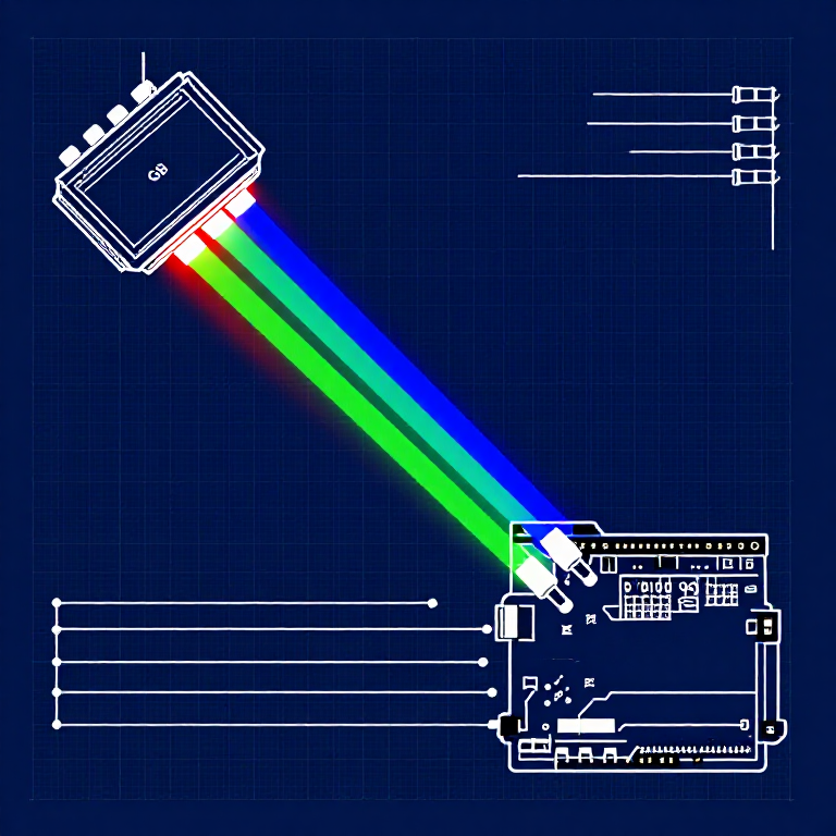
Hardware Hookup
Hardware Hookup
Wiring Instructions
- Place the RGB LED in the breadboard. Identify pins from the flattened edge: Red, GND (longest), Green, Blue.
- Connect the GND pin (longest, second from left) to the GND rail.
- Connect the Red pin through a 330Ω resistor to Arduino Pin 9.
- Connect the Green pin through a 330Ω resistor to Arduino Pin 10.
- Connect the Blue pin through a 330Ω resistor to Arduino Pin 11.
Pins 9, 10, and 11 are all PWM-capable (marked with ~ on the board).
Materialien für diesen Schritt:
RGB LED (Common Cathode)1 Stück330 Ohm Resistor3 StückJumper Wires5 StückArduino Code
Arduino Code
Open the Arduino IDE and upload the following sketch to your Arduino board.
Materialien für diesen Schritt:
Benötigte Werkzeuge:
Test & Experiment
Test & Experiment
What You Should See
The LED cycles through 8 solid colors (off, red, green, blue, yellow, cyan, purple, white) for 1 second each, then smoothly fades through the entire color spectrum.
Troubleshooting
- Incorrect colors: With four pins close together, it's easy to misplace one. Double-check each connection.
- Red too bright: The red diode is often brighter. Try a higher-value resistor on the red pin, or reduce in code:
analogWrite(RED_PIN, redIntensity/3).
Experiments to Try
- Add a potentiometer to control which color is displayed.
- Create your own color sequences — try a "sunrise" effect (dark red → orange → yellow → white).
Materialien
6- €90.00
- Platzhalter
- €3.00
CC0 Gemeinfrei
Dieser Blueprint ist unter CC0 veröffentlicht. Sie dürfen dieses Werk für jeden Zweck frei kopieren, ändern, verbreiten und verwenden, ohne um Erlaubnis zu fragen.
Unterstützen Sie den Maker, indem Sie Produkte über seinen Blueprint kaufen, wo er eine Maker-Provision von Anbietern festgelegt, verdient. Oder erstellen Sie eine neue Iteration dieses Blueprints und verbinden Sie ihn in Ihrem eigenen Blueprint, um Einnahmen zu teilen.