KUNST
SCHÖNHEIT & WELLNESS
HANDWERK
KULTUR & GESCHICHTE
UNTERHALTUNG
UMFELD
ESSEN & GETRÄNKE
REVERSE ENGINEERING
WISSENSCHAFTEN
SPORT
TECHNOLOGIE
WEARABLES
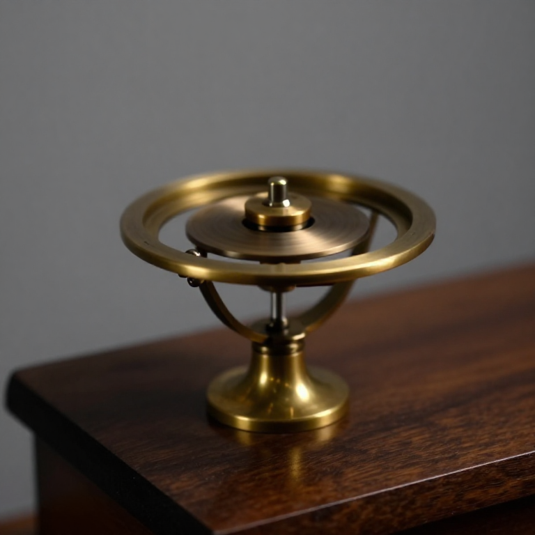


The Sperry Gyro Autopilot
A gyrocompass tells a ship where north is and then stops. Elmer Sperry's question from about 1910 was what happens if the gyro does not merely report the attitude but ACTS on it - if the instrument is wired to the controls, so the machine flies itself.
His son Lawrence demonstrated the answer at the aircraft safety competition at Bezons, near Paris, on 18 June 1914: he flew a Curtiss flying boat past the judges with both hands in the air while his mechanic walked out along the wing, and the gyroscopic stabiliser held it level. It won the prize and it is the first machine that flew itself.
The control lesson is the one that recurs in every blueprint after it. Feed the roll ANGLE back to the ailerons and you have not built a stabiliser, you have built a torsion spring: push the aircraft off level and it comes back, overshoots, comes back again. An early aeroplane's aerodynamic damping is worth a damping ratio of only about 0.3, so the machine wallows for half a minute after every gust. Nothing in that loop takes energy out.
The fix is to feed back the RATE of roll as well - how fast it is getting worse, not just how bad it is - and the beauty of it is that a spinning gyro in gimbals gives you both from one instrument. The angle comes from the gyro staying put while the aircraft moves around it; the rate comes from the torque it takes to precess it. The second term costs no extra sensor, only the wit to use what the first one already produced.
There is a limit that no amount of gain gets past. A stiff loop asks for more aileron than the surface has, and a control surface hard against its stop is not in a feedback loop at all.
Erfahren
4 hours
Anweisungen
1
1
A plank on a bearing
A plank on a bearing
Pivot a 400 mm plywood beam on a single ball bearing so it rolls freely about its long axis, and screw the IMU flat at the centre.
Mount the servo to the frame and link its horn to one end of the beam with a stiff wire, so the servo can tilt the beam a few degrees either way. Balance it until it sits level with the servo centred - an unbalanced rig hides everything you are about to measure.
Materialien für diesen Schritt:
 Sperrholzplatte1 Blatt
 Kugellager1 Stück
 Klaviersaitendraht200 mm
 Sechskantmutter8 Stück
Benötigte Werkzeuge:
 Akkubohrschrauber
 Lineal
 Digitaler Messschieber 6 Zoll
 Schraubendreher-Satz
2
2
The stabiliser sketch
The stabiliser sketch
One hundred loops a second: read the angle, read the rate, command the servo. The two gains at the top are the whole experiment.
Leave `KD` at zero first - that is a 1912 attitude-only stabiliser, and it will wallow. Then raise it and watch the wallow die.
gyro_stabiliser.inocpp
Materialien für diesen Schritt:
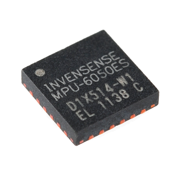 3-Axis Gyro/Accelerometer IC - MPU-60501 Stück
 Servomotor-Set für Arduino1 Packung
 Dupont-Steckkabelsatz (Stecker-Buchse)1 Set
Benötigte Werkzeuge:
 Arduino Uno R3
 Steckbrett
 Desktop-Computer
 Labornetzgerät
3
3
Spring, stabiliser, and four ways to stay level
Spring, stabiliser, and four ways to stay level
Jupyter-Notebook wird geladen …
Benötigte Werkzeuge:
Desktop-Computer4
4
Compendium: what the gyro cannot tell you
Compendium: what the gyro cannot tell you
A gyroscope holds a direction in space, not relative to the earth, so over an hour it drifts - a few degrees at best on 1914 bearings. Left alone the autopilot would fly a steadily banking turn while insisting the wings were level. Sperry's erection system fixes it with pendulous weights or air jets that slowly torque the gyro back towards the local vertical, a second and much slower feedback loop wrapped around the first. The sketch here does the same thing digitally: the complementary filter trusts the gyro over one second and the accelerometer over a minute, because one is smooth and drifts while the other is noisy and does not.
That second loop has a failure mode built into it. An accelerometer cannot distinguish gravity from acceleration, so in a steady coordinated turn the apparent vertical tilts with the aircraft and the erection system patiently teaches the gyro that the banked attitude is level. Real autopilots cut the erection out whenever a turn is detected. It is worth recognising because the same trap catches every balancing robot ever built for the same reason: the reference the slow loop trusts is only trustworthy while the vehicle is not doing anything interesting.
Materialien
7- 1 BlattPlatzhalter
- Platzhalter
- 200 mmPlatzhalter
- 8 StückPlatzhalter
- 3-Axis Gyro/Accelerometer IC - MPU-605010% Provision1 Stück€11.16
- 1 PackungPlatzhalter
- Platzhalter
Benötigte Werkzeuge
8- 1 vendor sell this, none ship to you yetPlatzhalter
- Platzhalter
- Platzhalter
- Platzhalter
- 1 vendor sell this, none ship to you yetPlatzhalter
- 1 vendor sell this, none ship to you yetPlatzhalter
- Platzhalter
- Platzhalter
Geschätzte Gesamtkosten
Was der Maker gekauft hat. Materialien ohne Preis besorgst du dort, wo du sie kaufst.
Verwandte Blueprints
Diese Blueprints teilen Wissen — Techniken, Materialien oder Prinzipien



CC0 Gemeinfrei
Dieser Blueprint ist unter CC0 veröffentlicht. Sie dürfen dieses Werk für jeden Zweck frei kopieren, ändern, verbreiten und verwenden, ohne um Erlaubnis zu fragen.
Unterstützen Sie den Maker, indem Sie Produkte über seinen Blueprint kaufen, wo er eine Maker-Provision von Anbietern festgelegt, verdient. Oder erstellen Sie eine neue Iteration dieses Blueprints und verbinden Sie ihn in Ihrem eigenen Blueprint, um Einnahmen zu teilen.