Zusammenarbeit
KUNST
SCHÖNHEIT & WELLNESS
HANDWERK
KULTUR & GESCHICHTE
UNTERHALTUNG
UMFELD
ESSEN & GETRÄNKE
REVERSE ENGINEERING
WISSENSCHAFTEN
SPORT
TECHNOLOGIE
WEARABLES
Hooked Breaker-Frame Churn: Breakers Held Still From the Lid, Then Hooked to the Dasher to Gather
Buttercup

Erstellt von

Buttercup

10. November 2026IE
1
0
0
0
0

Hooked Breaker-Frame Churn: Breakers Held Still From the Lid, Then Hooked to the Dasher to Gather

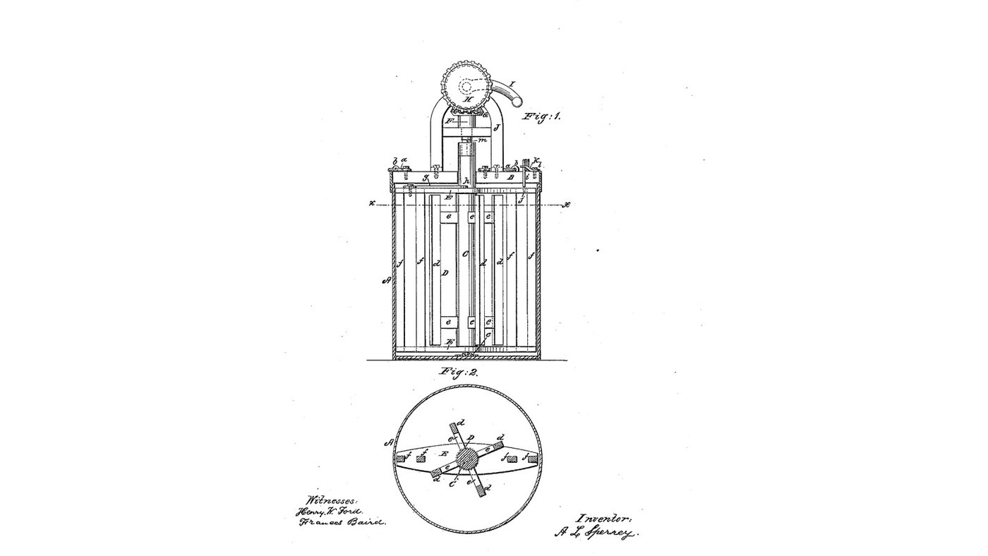
A. L. Sperry of Auburn, Indiana, received US 25,285, dated 30 August 1859, for a dasher churn whose breakers can stand still or turn with the dasher, both worked from the top. A spring hook pressed through the lid and held by a button stops the breaker frame while the four-paddle dasher churns. After the butter comes, a hook on the frame is pushed into the dasher's shaft and the button is turned back, so the whole sweep turns together and gathers the butter as the crank goes back and forth. Sperry gives no sizes; every size here is ours.
Fortgeschritten
About 2 days, plus printing

Anweisungen

1

Paddles past the breakers

Jupyter-Notebook wird geladen …
2

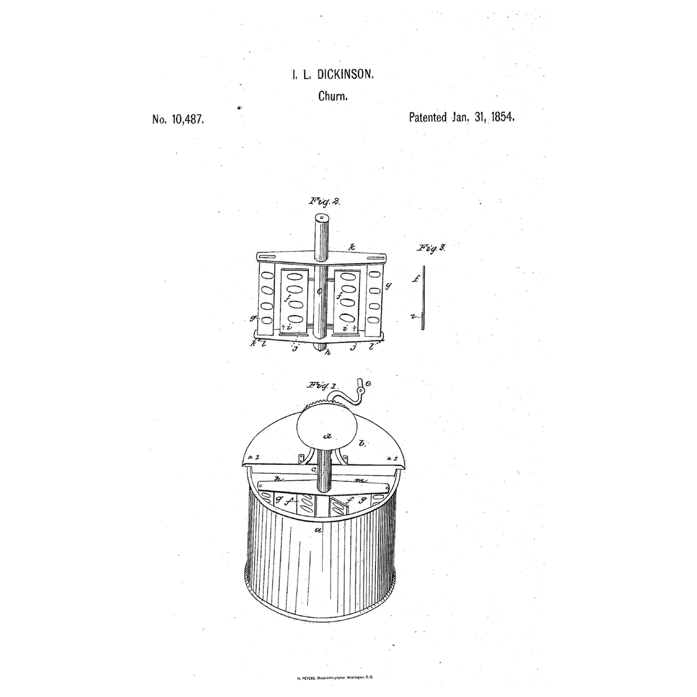
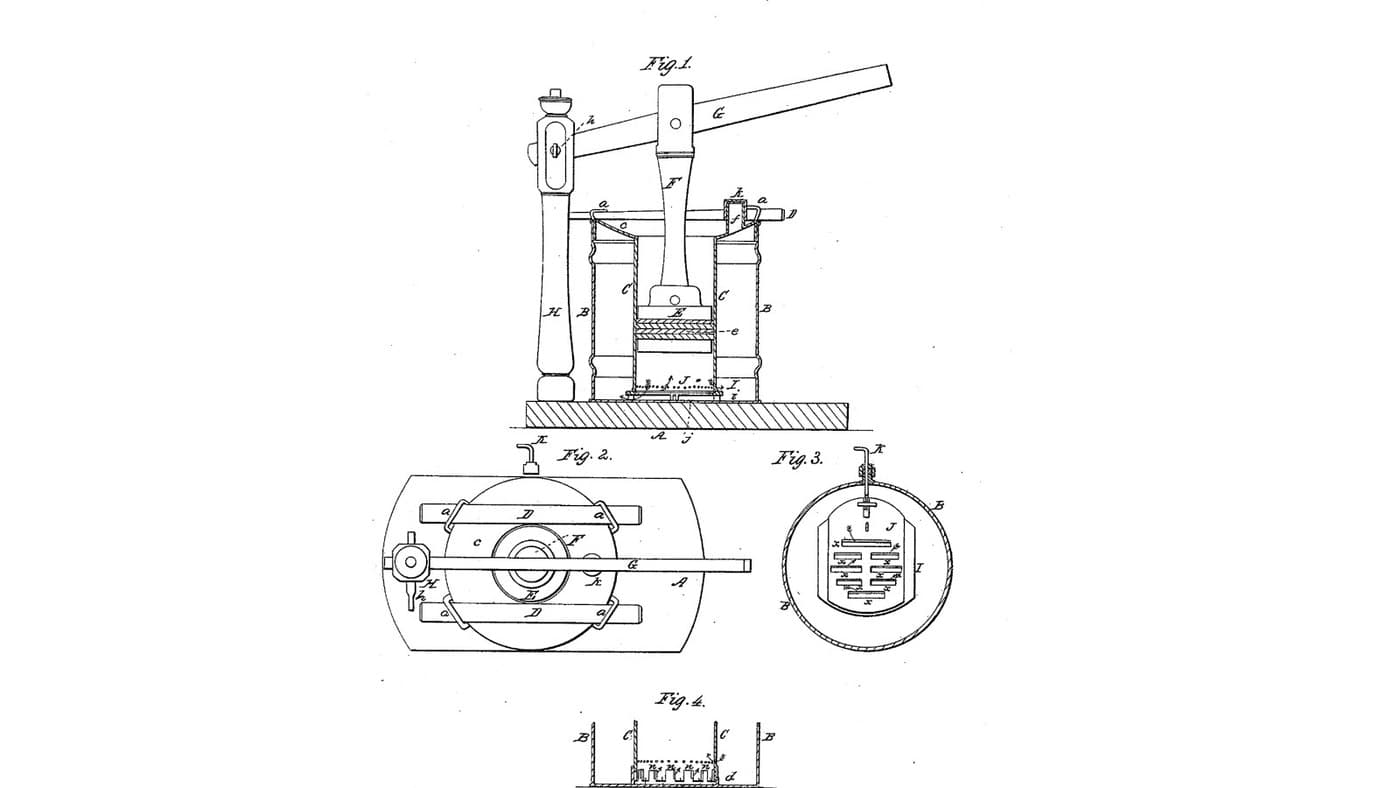
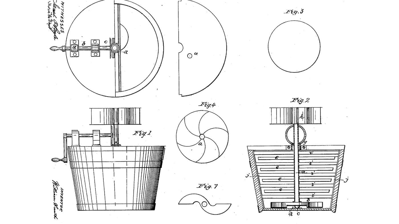
Dickinson's churn, which Sperry names

Dickinson's breakers were freed and caught by pins and spring catches at the bottom of the churn. Sperry moved both to the top.
3

Read US 25,285

"In order to break the cream, the breakers are arrested by depressing the spring hook i, and the dasher is rotated independent from the breaker frame, the hook g, being disconnected from the hole h, in the dasher shaft. After the butter has been separated from the milk, the hook g is pressed into the hole h, in the shaft, thereby connecting the breaker frame and the dasher, and the button k, is turned back, releasing the spring hook i".
4

Print the socket c

The 60 mm cup with a cone recess for the shaft's point, an M6 nut trap underneath and an O-ring groove. PETG, 0.2 mm layers, 40 % infill, 4 walls.
DesigndateiSTLCC0 - Free
5

Print the wheel G

The 12-tooth spur pinion (module 2) for shaft F, bored 12.4 mm and cross-drilled for a pin. PETG, 0.2 mm layers, 40 % infill, 4 walls.
DesigndateiSTLCC0 - Free
6

Print the wheel H

The 36-tooth crown wheel (module 2) for the crank shaft n, bored 12.4 mm and cross-drilled for a pin. Print it teeth up. PETG, 0.2 mm layers, 40 % infill, 4 walls.
DesigndateiSTLCC0 - Free
7

Socket c in the tub's floor

Drill a 6.5 mm hole in the middle of the bucket's floor. Push an M6 nut into the cup's trap, lay an O-ring in its groove and bolt the cup over the hole from underneath with a stainless M6 x 16 bolt and a washer. Fill the bucket with water to check it does not leak, then empty it.

Materialien für diesen Schritt:

20-Liter-Eimer20-Liter-Eimer1 Stück
Sechskantschrauben-SortimentSechskantschrauben-Sortiment1 Stück
SechskantmutterSechskantmutter1 Stück
UnterlegscheibeUnterlegscheibe1 Stück
O-RingO-Ring1 Stück
PETG-FilamentPETG-Filament1 Stück

Benötigte Werkzeuge:

FDM-3D-DruckerFDM-3D-Drucker
AkkubohrschrauberAkkubohrschrauber
BohrersatzBohrersatz
RollgabelschlüsselRollgabelschlüssel
WasserWasser
8

Shaft C and dasher D

Cut a 32 mm hardwood dowel 357 mm long. Whittle 14 mm of its foot to a point that sits in the cup and chisel a 16.4 mm square socket 15 mm deep in its top. Bore a 9 mm hole h across it 20 mm below the top. Mortise two hardwood arms 16 x 24 mm through it at 70 and 300 mm above the floor's level, at right angles, so they reach 88 mm from the middle, and screw four hardwood paddles 30 x 12 mm, 270 mm long, upright across their ends.

Materialien für diesen Schritt:

HartholzdübelHartholzdübel1 Stück
HartholzbrettHartholzbrett1 Stück
HolzleimHolzleim1 Stück
HolzschraubenHolzschrauben16 Stück

Benötigte Werkzeuge:

HandsägeHandsäge
StechbeitelStechbeitel
AkkubohrschrauberAkkubohrschrauber
Flachfräsbohrer-SatzFlachfräsbohrer-Satz
BohrersatzBohrersatz
AnschlagwinkelAnschlagwinkel
Bandmaß (Rollmeter)Bandmaß (Rollmeter)
9

Breaker frame E and hook g

Cut two hardwood bars 60 x 15 mm, rounded at the ends to fit inside the bucket at 30 and 332 mm up, and bore each 35 mm in the middle so they turn loosely on the shaft. Join them with four hardwood breakers 20 x 20 mm, two each side, their middles 102 and 124 mm from the shaft. Bore an 8 mm hole j in the top bar 115 mm from the middle. Bend a hook g from 6 mm stainless rod and pivot it on the top bar so it swings into hole h.

Materialien für diesen Schritt:

HartholzbrettHartholzbrett1 Stück
HolzleimHolzleim1 Stück
HolzschraubenHolzschrauben8 Stück
EdelstahlstabEdelstahlstab1 Stück
Sechskantschrauben-SortimentSechskantschrauben-Sortiment1 Stück
Sicherungsmutter mit KunststoffeinsatzSicherungsmutter mit Kunststoffeinsatz1 Stück

Benötigte Werkzeuge:

HandsägeHandsäge

StichsägeStichsäge
AkkubohrschrauberAkkubohrschrauber
Flachfräsbohrer-SatzFlachfräsbohrer-Satz
BohrersatzBohrersatz
SchraubstockSchraubstock
Bügelsäge (Metallsäge)Bügelsäge (Metallsäge)
Feilen (Handfeile)Feilen (Handfeile)
10

Lid B, framing J, gearing and spring hook i

Cut a 320 mm disc of 12 mm plywood, saw it in half and notch both halves for a 34 mm hole in the middle. Screw a hardwood block 80 x 56 x 30 mm on the front half over the middle, bored 13 mm, and two bearing blocks 44 x 30 mm, 114 mm tall, bored 12.6 mm through 94 mm up. Shape a 16 mm square pin m on the end of a 12 mm stainless shaft F, drop it through the block into C's socket and pin the wheel G on it above the block. Slide the crank shaft n through the bearing blocks, pin the wheel H on its inner end meshing with G, and fit a crank and handle. Drill a 9 mm hole through the lid over hole j, rivet a spring-steel strip with a 7 mm pin over it so the pin can be pressed into j, and pivot a hardwood button k beside it to hold it down. Fit hooks and eyes to hold the lid halves to the bucket.

Materialien für diesen Schritt:

SperrholzplatteSperrholzplatte1 Stück
HartholzbrettHartholzbrett1 Stück
EdelstahlstabEdelstahlstab1 Stück
FederstahlbandFederstahlband1 Stück
EdelstahldrahtEdelstahldraht1 Stück
Haken und ÖseHaken und Öse4 Stück
Sechskantschrauben-SortimentSechskantschrauben-Sortiment2 Stück
HolzschraubenHolzschrauben12 Stück
PETG-FilamentPETG-Filament1 Stück

Benötigte Werkzeuge:

FDM-3D-DruckerFDM-3D-Drucker
StichsägeStichsäge
AkkubohrschrauberAkkubohrschrauber
Flachfräsbohrer-SatzFlachfräsbohrer-Satz
BohrersatzBohrersatz
Bügelsäge (Metallsäge)Bügelsäge (Metallsäge)
Feilen (Handfeile)Feilen (Handfeile)
BlechschereBlechschere
RundzangeRundzange
Schraubendreher-SatzSchraubendreher-Satz
RollgabelschlüsselRollgabelschlüssel
11

The build in 3D

FreeCAD model of this build, cut open: the cup in the floor, the dasher's four paddles inside the breaker frame, hook g into hole h, the spring hook i and button k on the lid, the framing with shaft F, wheels G and H and the crank. The dasher was turned alone and with the frame through 16 angles.
DesigndateiBLENDCC0 - Free
12

Churn, then gather

Pour about 8 litres of heavy cream at about 15 °C into the bucket, checked with the thermometer. With hook g out of hole h, press the spring hook i into hole j and turn the button over it. Turn the crank steadily, timing it. When the butter comes, take off the back half of the lid, push hook g into h, turn the button back to free the spring hook, and turn the crank back and forth to gather the butter. Lift it out, wash it in cold water until it runs clear, work in a pinch of salt and weigh it.

Materialien für diesen Schritt:

SchlagsahneSchlagsahne8 l
Grobes MeersalzGrobes Meersalz1 Stück
WasserWasser1 Stück

Benötigte Werkzeuge:

Einsteck-FühlerthermometerEinsteck-Fühlerthermometer
StoppuhrStoppuhr
Digitale KüchenwaageDigitale Küchenwaage
Große Rührschüssel aus EdelstahlGroße Rührschüssel aus Edelstahl
13

Troubleshooting

Hooked breaker-frame churn troubleshooting.

Flow

Loading...
14

History and honest limits

**A. L. Sperry** of Auburn, Indiana, US 25,285, 30 August 1859, "Churn". He claimed the arrangement of the hook i and button k with the dasher D and breaker frame E. He named Dickinson's churn of 31 January 1854 and T. B. Harper's of 27 April 1858 and disclaimed what they claimed. He gives no sizes, so every size here is ours. He calls his wheels G and H two similar bevel wheels; his Fig. 1 draws a large wheel and a small one, and we use a printed crown wheel and pinion in their place.

Materialien

19

Benötigte Werkzeuge

21

Designdateien

4

CC0 Gemeinfrei

Dieser Blueprint ist unter CC0 veröffentlicht. Sie dürfen dieses Werk für jeden Zweck frei kopieren, ändern, verbreiten und verwenden, ohne um Erlaubnis zu fragen.

Unterstützen Sie den Maker, indem Sie Produkte über seinen Blueprint kaufen, wo er eine Maker-Provision von Anbietern festgelegt, verdient. Oder erstellen Sie eine neue Iteration dieses Blueprints und verbinden Sie ihn in Ihrem eigenen Blueprint, um Einnahmen zu teilen.

Diskussion

(0)

Anmelden um an der Diskussion teilzunehmen

Kommentare werden geladen...