Zusammenarbeit
KUNST
SCHÖNHEIT & WELLNESS
HANDWERK
KULTUR & GESCHICHTE
UNTERHALTUNG
UMFELD
ESSEN & GETRÄNKE
REVERSE ENGINEERING
WISSENSCHAFTEN
SPORT
TECHNOLOGIE
WEARABLES
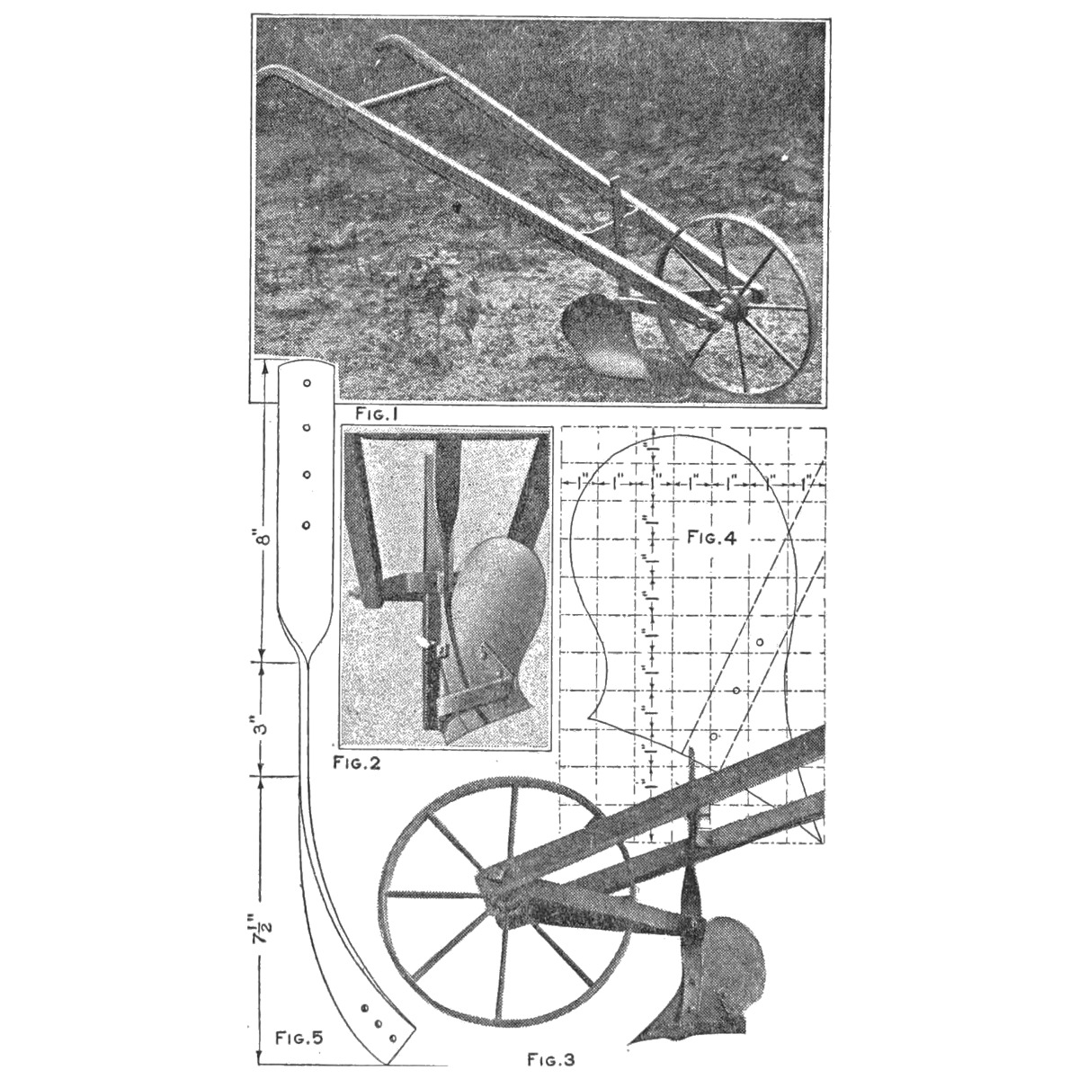


Garden Hand Plow From Scrap: Wheelbarrow Wheel, Ripped Spruce Handles and a Shovel-Blade Moldboard (Boy Mechanic, 1919)
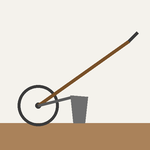
T. T. Sturgeon's hand plow from The Boy Mechanic, Book 3 (1919), "worth about $5 at an outlay of 25 cents": a 16 in wheelbarrow wheel, handles ripped from one spruce strip, iron-strap braces, an adjustable vertical strap, and a moldboard and share cut from an old shovel blade to his grid pattern.
Fortgeschritten
About 1 day
Anweisungen
1
1
His cut list in centimetres
His cut list in centimetres
Jupyter-Notebook wird geladen …
2
2
Read The Boy Mechanic, Book 3
Read The Boy Mechanic, Book 3
"The labor of spading a garden of even moderate size is sufficient to warrant the person who undertakes the job in making a hand plow like that shown in the illustration."
3
3
Make the handles
Make the handles
Mark both handles on a 7/8 by 4 in spruce strip 5 ft long, one curved grip at each end on opposite edges. Cut the curves with a keyhole saw, then rip the board into the two handles; smooth them and trim the grips with a sharp knife. Cut a section of broomstick for the upper brace.
Materialien für diesen Schritt:
 Hartholzbrett1 Stück
 Besen1 Stück
Benötigte Werkzeuge:
 Laubsäge (Schweifsäge)
 Längsschnittsäge
 Ledermesser
 Bleistift
4
4
Make the iron parts
Make the iron parts
Lower brace: iron 1/4 by 1-1/4 by 12 in, drilled for 1/4 in bolts, bent at right angles 1-1/2 in from each end, with a 1/4 in hole at the middle. Vertical support: 1/4 by 1-1/4 by 18 in, four 1/4 in adjusting holes 1 in apart at the top, three 1/4 in holes at the bottom for the moldboard, and a 5/16 in hole at the 7-1/2 in mark. Two braces 14 in long of 1/4 by 1-1/4 in, a 3/8 in hole at the front of each for the 3/8 by 10 in axle bolt and a 5/16 in hole at the other end, each 1 in from the end. Landside: 1/8 by 3/4 by 12 in.
Materialien für diesen Schritt:
 Baustahl-Flachstahl3 Stück
Benötigte Werkzeuge:
 Bügelsäge (Metallsäge)
 Handbohrer
 Schraubstock
 Hammer
 Feilen (Handfeile)
 Bandmaß (Rollmeter)
5
5
Cut the moldboard
Cut the moldboard
Draw his moldboard (Fig. 4) on cardboard ruled in 1 in squares, tracing the outline square by square, and mark the bolt holes. Trace it on an old shovel blade, using the thickest part for the point of the share. Cut it out, smooth the edges and sharpen the cutting edge. Drill for 1/4 in bolts to the vertical strap and 3/16 in bolts to the landside.
Materialien für diesen Schritt:
 Schaufel1 Stück
 Schablonen aus Pappe1 Stück
Benötigte Werkzeuge:
BleistiftBügelsäge (Metallsäge) WinkelschleiferFeilen (Handfeile)Handbohrer
6
6
Shape and assemble
Shape and assemble
Curve the moldboard and fit it to the supports as in Figs. 1-3. Bend the 12 in landside strip under the moldboard and bolt it on. Assemble on the 16 in wheel and 3/8 in axle bolt, with wheel and landside in line (Fig. 2) and the landside's rear edge raised slightly (Fig. 3); set the vertical strap's height for the operator in its adjusting holes. Paint the plow and oil the smoothed cutting parts.
Materialien für diesen Schritt:
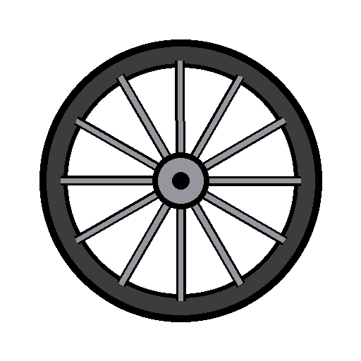 Schubkarrenrad1 Stück
 Schlossschraube6 Stück
 Sechskantmutter6 Stück
 Unterlegscheibe6 Stück
 Ölfarbe1 Stück
 Maschinenöl1 Stück
Benötigte Werkzeuge:
SchraubstockHammer Breiter Pinsel
7
7
Troubleshooting
Troubleshooting
Garden plow troubleshooting.
Flow
Loading...
8
8
History and honest limits
History and honest limits
From "Garden Plow Made of Pick-Up Material" by T. T. Sturgeon, in **The Boy Mechanic, Book 3**, Popular Mechanics, 1919 (Project Gutenberg 71856; checked on the archive.org scan boymechanic0003unse, pp. 227-228). The moldboard shape is his Fig. 4 grid. The keyhole saw is a coping saw here; the tools and metric figures are ours.
Materialien
11- 1 StückPlatzhalter
- 1 StückPlatzhalter
- 3 StückPlatzhalter
- 1 StückPlatzhalter
- 1 StückPlatzhalter
- 1 StückPlatzhalter
- 6 StückPlatzhalter
- 6 StückPlatzhalter
- 6 StückPlatzhalter
- 1 StückPlatzhalter
- 1 StückPlatzhalter
Benötigte Werkzeuge
12- Platzhalter
- Platzhalter
- Platzhalter
- 1 vendor sell this, none ship to you yetPlatzhalter
- Platzhalter
- Platzhalter
- Platzhalter
- Platzhalter
- Platzhalter
- 1 vendor sell this, none ship to you yetPlatzhalter
- 1 vendor sell this, none ship to you yetPlatzhalter
- Platzhalter
Dieser Bauplan stellt her
Verwandte Blueprints
Diese Blueprints teilen Wissen — Techniken, Materialien oder Prinzipien
CC0 Gemeinfrei
Dieser Blueprint ist unter CC0 veröffentlicht. Sie dürfen dieses Werk für jeden Zweck frei kopieren, ändern, verbreiten und verwenden, ohne um Erlaubnis zu fragen.
Unterstützen Sie den Maker, indem Sie Produkte über seinen Blueprint kaufen, wo er eine Maker-Provision von Anbietern festgelegt, verdient. Oder erstellen Sie eine neue Iteration dieses Blueprints und verbinden Sie ihn in Ihrem eigenen Blueprint, um Einnahmen zu teilen.