KUNST
SCHÖNHEIT & WELLNESS
HANDWERK
KULTUR & GESCHICHTE
UNTERHALTUNG
UMFELD
ESSEN & GETRÄNKE
REVERSE ENGINEERING
WISSENSCHAFTEN
SPORT
TECHNOLOGIE
WEARABLES

The Screw Compressor: A Built-In Ratio, and the Cost of the Wrong One
Two helical rotors — a male with convex lobes and a female with concave flutes — mesh inside a close-fitting casing. Air is drawn into the spaces between the lobes at one end, sealed off as the rotors turn, and carried along the axis in pockets that shrink until they reach a port at the other end. There are no valves and nothing reciprocates, so it runs continuously and smoothly.
Alf Lysholm and Gustav Boestad in Sweden made the twin-screw compressor practical in the 1930s. Their 1936 patent is about a loss nobody had noticed: the two pockets that join to make one compression space start shrinking at different moments.
The screw compressor's defining habit is that it compresses by a FIXED ratio, set by where the discharge port is cut. This rung works out what that costs when the system runs at a different pressure — and shows the maker how to measure the pressure their system really needs before choosing one.
Erfahren
About 4 hours
Anweisungen
1
1
Read the patent: rotors, pockets and a hidden loss
Read the patent: rotors, pockets and a hidden loss
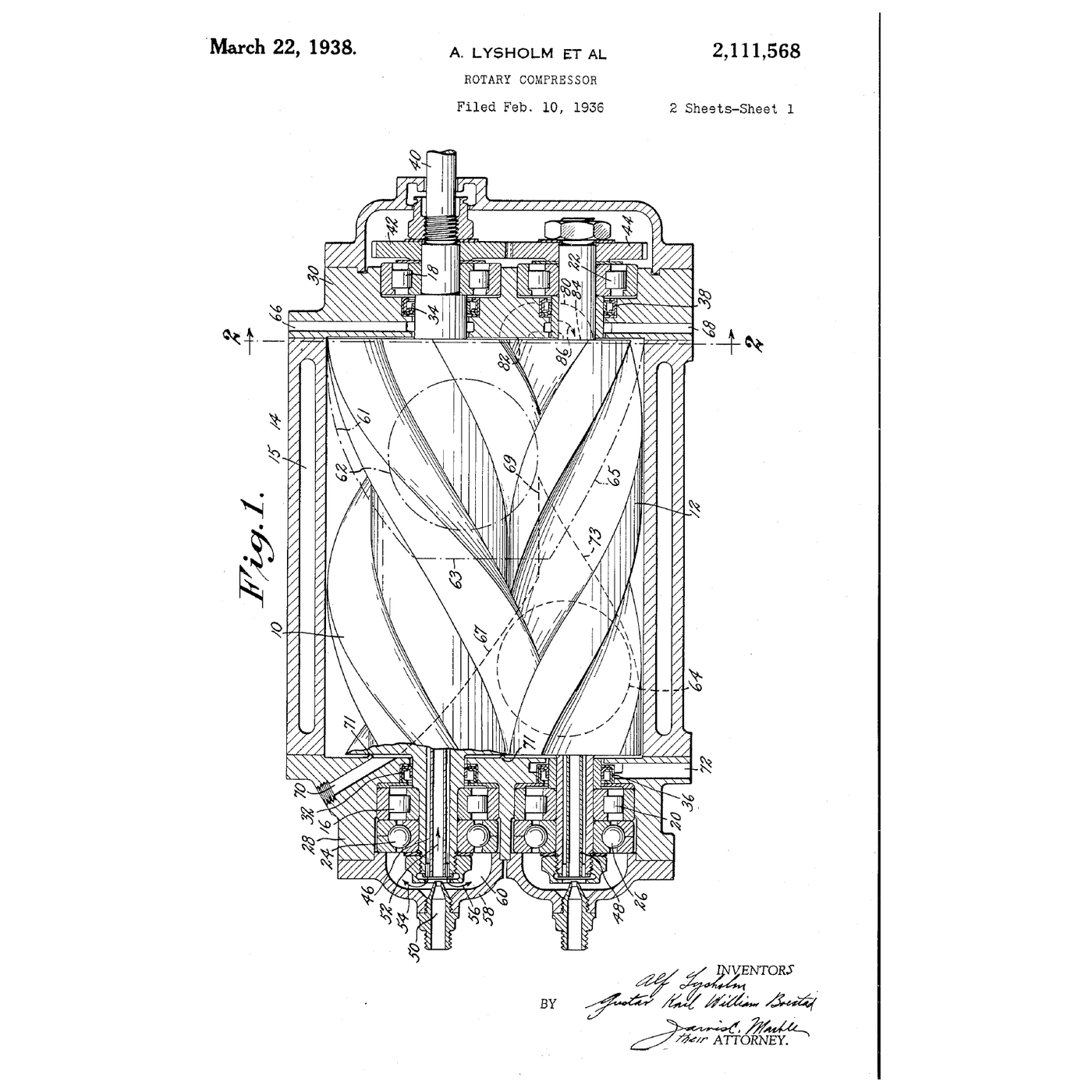
US 2,111,568 shows two rotors, 10 and 12, in a casing 14 — *"compressors of the rotary screw type in which two or more cooperating rotors"* provide compression spaces whose volume varies as they turn. Each rotor's lobes form pockets with the casing; a male pocket and a female pocket are *"brought into communication with each other and thereafter the two spaces work together as a common compression space"* until the outlet port opens.
The discovery is the next sentence: the reduction in volume of one pocket *"commences prior to"* that of its partner. So the two are at different pressures when they meet. The cure: a **pressure relief passage** that keeps the early pocket from compressing on its own. In the preferred form the end wall is shaped so that pocket P *"remains in communication with the suction space"* until the pockets join, so that *"no compression is effected prior to the time of direct communication"* and the two then compress together. The claims also cover a passage connecting the two pockets directly *"before direct communication between the pockets is established"*.
Find on the drawing: the two rotors, the inlet and outlet, and the shaped end wall that keeps pocket P open to suction. That porting is the invention; the screw compressor itself was already known.
2
2
One compression space, one turn
One compression space, one turn
Blockly-Arbeitsbereich
Loading Blockly workspace...
3
3
Built-in ratio against system pressure
Built-in ratio against system pressure
Jupyter-Notebook wird geladen …
4
4
Measure what your system actually needs
Measure what your system actually needs
Before choosing any compressor, find the pressure the work needs — not the pressure the compressor can make.
Fit a pressure gauge at the far end of the air line, right at the tool, through a tee. Run each tool you use and read the gauge while it works. Most air tools are rated for about 6 bar (90 psi) at the tool; many jobs run happily below that. Then read the pressure at the compressor at the same moment: the difference is what the hoses, couplings and filters lose, and it is often more than a bar on a long, narrow line.
Now set the regulator at the compressor down, step by step, until the hardest-working tool starts to slow. The pressure just above that, plus the line loss, is your real system pressure. Converted to an absolute ratio (add 1 bar to the gauge reading), it is the number the notebook's table wants — and every bar you did not need is work the compressor was doing for nothing.
Materialien für diesen Schritt:
 PVC-Fittingsortiment1 Set
 PTFE-Gewindedichtband1 Rolle
Benötigte Werkzeuge:
 Manometer
 Druckminderer
 Luftkompressor
 Stoppuhr
 Rollgabelschlüssel
5
5
The pocket mismatch in numbers
The pocket mismatch in numbers
Jupyter-Notebook wird geladen …
6
6
It runs hot or trips: find out why
It runs hot or trips: find out why
The usual causes of a screw compressor shutting down on high discharge temperature, in the order to check them. On an oil-flooded machine the oil is the coolant, so most of them are about the oil.
Flow
Loading...
7
7
History and context
History and context
**US 2,111,568, 'Rotary Compressor', Alf Lysholm of Stockholm and Gustav Karl William Boestad of Lidingö, Sweden; application filed 10 February 1936 (Serial 63,160), claiming a Swedish filing of 12 February 1935; granted 22 March 1938.** The specification also refers to related US applications, Serial 44,935 of 14 October 1935 and Serial 183,664 of 6 January 1938, filed as a continuation in part.
Lysholm worked on rotary machines at the Ljungström steam-turbine company in Stockholm, and his rotor-profile work there is the root of the twin-screw compressor. The early machines ran dry, with timing gears keeping the rotors from touching. Injecting oil into the compression space came later: the oil seals the clearances, carries the heat of compression away and lets one rotor drive the other directly. The oil-flooded screw is now the standard factory and workshop compressor above a few kilowatts.
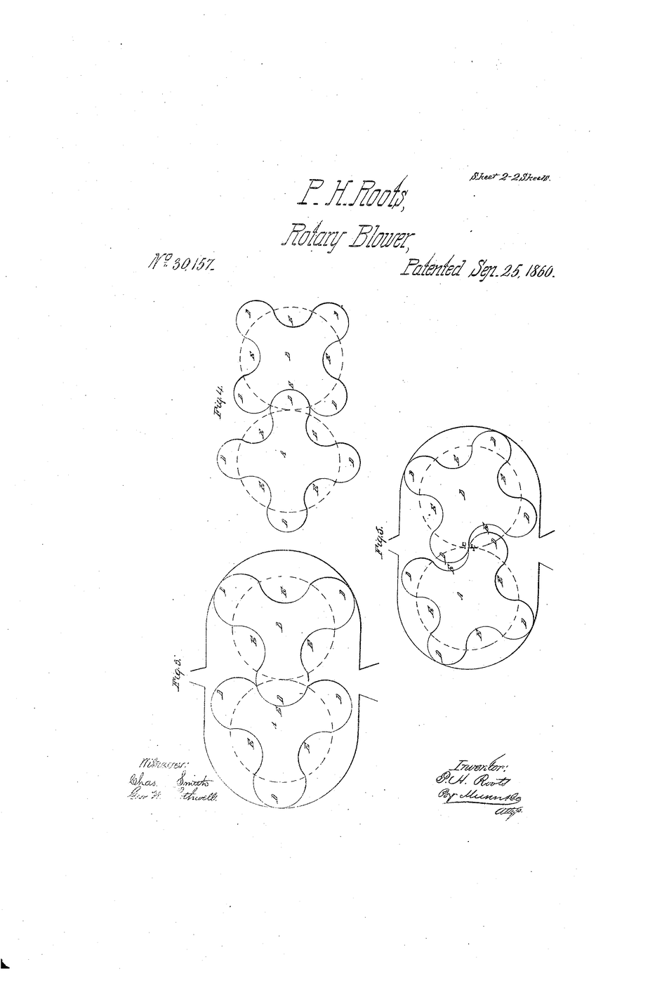
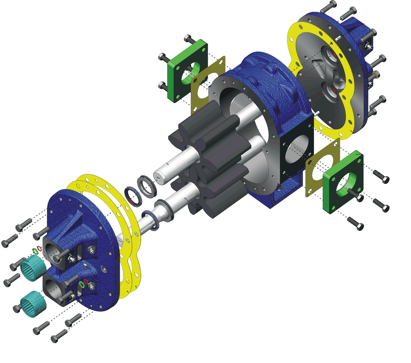
Its relatives here are the Roots blower (two lobed rotors that move gas but do not compress it inside — all the compression happens as the pocket opens to the pipe), the gear pump, and the scroll compressor, which shares the fixed built-in ratio.
**Honest limits.** The built-in ratio is fixed, so it is efficient over a narrow band of system pressures. The rotor profiles are difficult to cut and to measure. Oil-flooded machines need an oil separator and still carry some oil into the air. And it is poor at part load unless it has a variable-speed drive — running unloaded still costs power.
Materialien
2- 1 SetPlatzhalter
- 1 RollePlatzhalter
Benötigte Werkzeuge
5- Platzhalter
- Platzhalter
- 1 vendor sell this, none ship to you yetPlatzhalter
- Platzhalter
- Platzhalter
Verwandte Blueprints
Diese Blueprints teilen Wissen — Techniken, Materialien oder Prinzipien
Roots Blower
von Karen
Mechanik
39
0
0
0
0
0
Gear Pump
von Karen
TECHNOLOGIE
40
0
0
0
0
0
Watt Indicator Diagram
von Martin
TECHNOLOGIE
69
0
0
0
0
0

Boyle's Law — Squeeze a Syringe of Air
von Charlie
Chemie
51
0
0
0
2
0
The Scroll Compressor: Two Spirals, One Orbiting, No Valves
von Emma
Mechanik
34
0
0
0
0
0
The Progressing-Cavity Pump: One Thread Fewer, and Nothing Is Squeezed
von Emma
Mechanik
37
0
0
0
0
0
CC0 Gemeinfrei
Dieser Blueprint ist unter CC0 veröffentlicht. Sie dürfen dieses Werk für jeden Zweck frei kopieren, ändern, verbreiten und verwenden, ohne um Erlaubnis zu fragen.
Unterstützen Sie den Maker, indem Sie Produkte über seinen Blueprint kaufen, wo er eine Maker-Provision von Anbietern festgelegt, verdient. Oder erstellen Sie eine neue Iteration dieses Blueprints und verbinden Sie ihn in Ihrem eigenen Blueprint, um Einnahmen zu teilen.