Colaboración
ARTE
BELLEZA Y BIENESTAR
ARTESANÍA
CULTURA E HISTORIA
ENTRETENIMIENTO
MEDIO AMBIENTE
COMIDA Y BEBIDAS
INGENIERÍA INVERSA
CIENCIAS
DEPORTES
TECNOLOGÍA
TECNOLOGÍA VESTIBLE
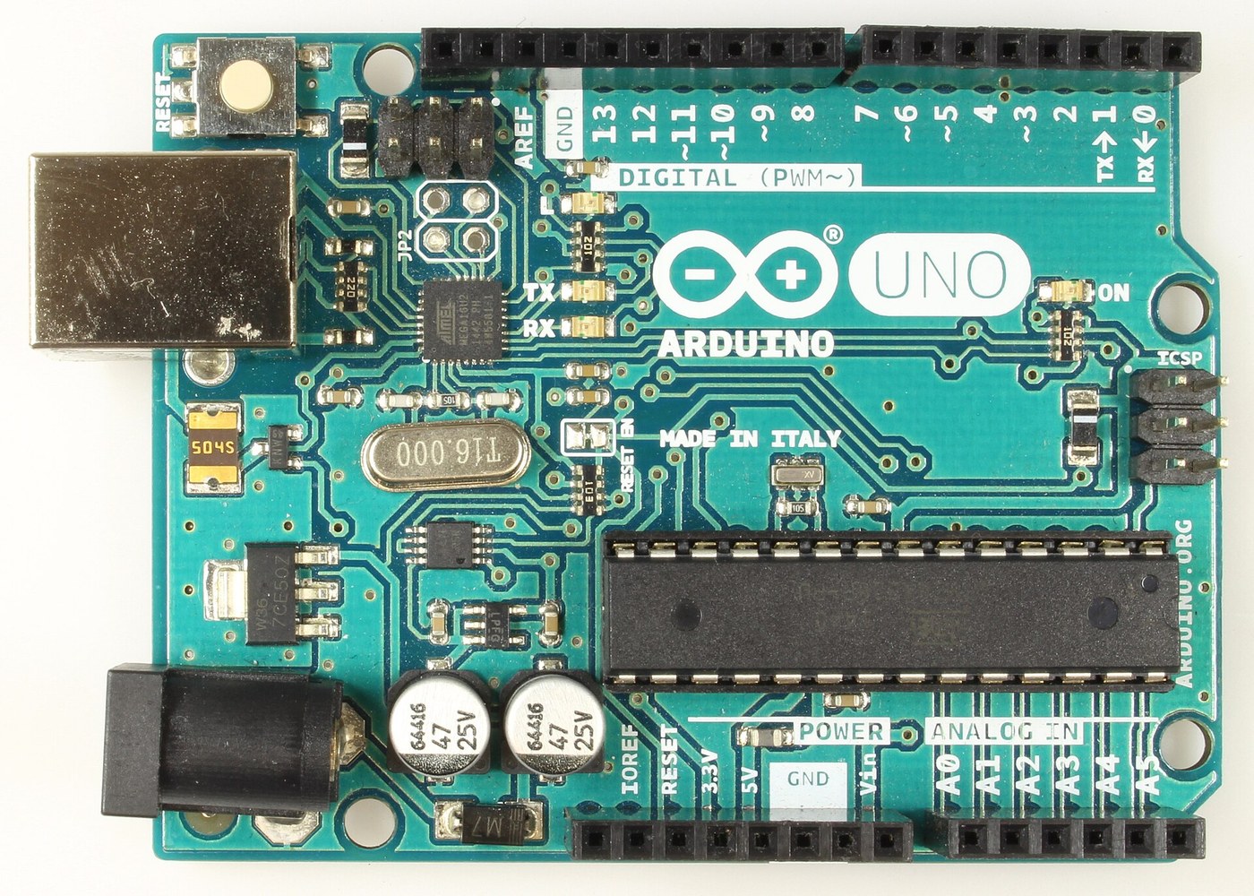


Arduino Uno R3: Assembled from Arduino's Open UNO-TH Rev3e Design Files and Flashed over ICSP
The Arduino Uno R3 is open hardware: Arduino publishes its schematic and board layout. This blueprint builds one from those files, part by part, then loads the firmware into its two processors.
Result: an Arduino Uno R3. An ATmega328P (16 MHz, 32 kB flash, 2 kB SRAM, 1 kB EEPROM) runs your programs; an ATmega16U2 turns USB into its serial link. It runs from USB (5.5 V at most) or 6-20 V at the DC jack.
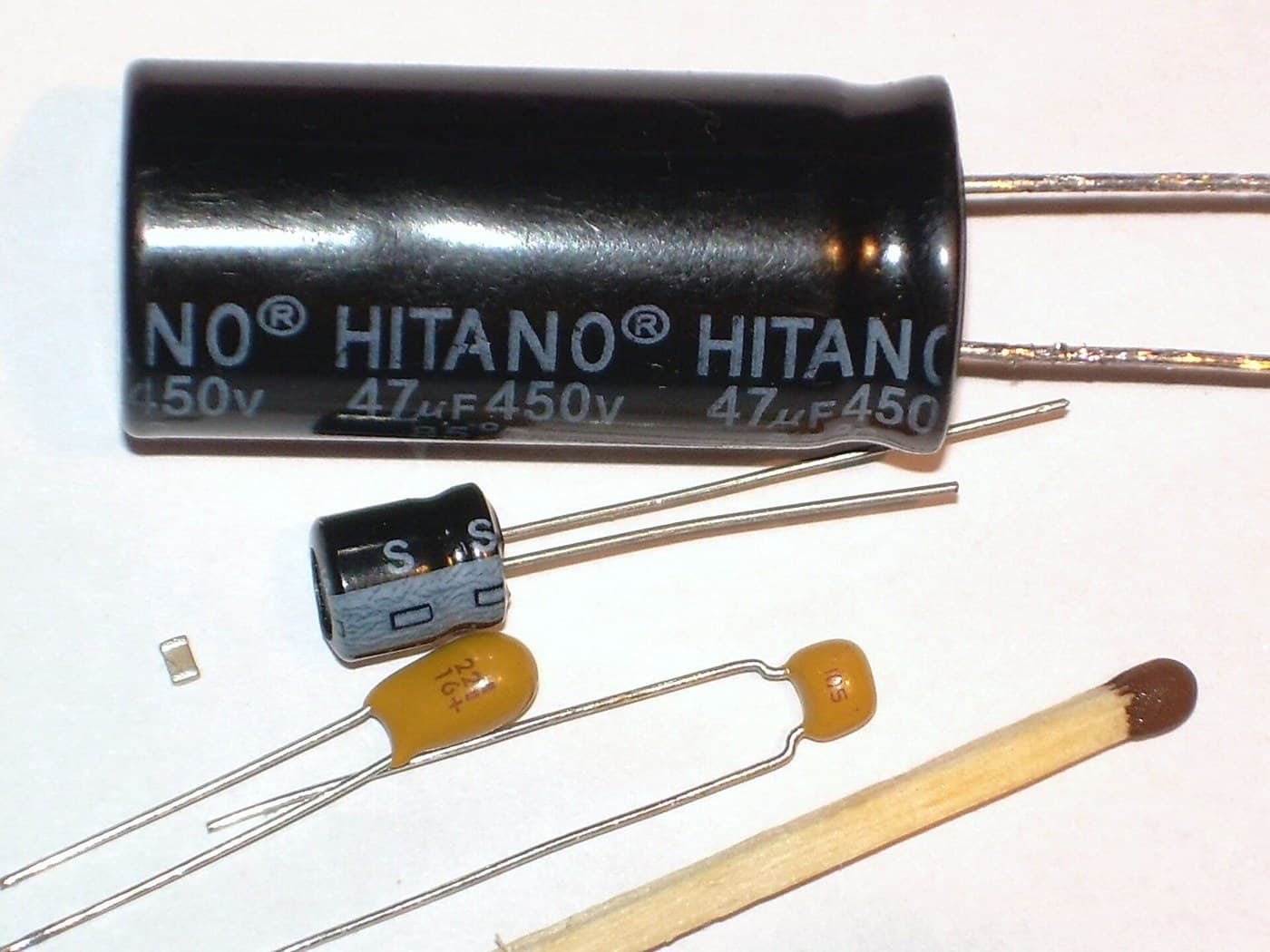
Source: Arduino UNO-TH_Rev3e design files and the A000066 schematic and datasheet (Arduino, CC BY-SA). Unknown: how every bought part is made; no public source in hand says. The soldering method is ours. Picture: Wikimedia Commons.
Avanzado
1 day
Instrucciones
1
1
Get the bare board
Get the bare board
Have the two-layer board made to Arduino's UNO-TH_Rev3e board layout (the .brd file of the design files). Check it against the schematic before fitting anything.
Materiales para este paso:
 Placa de circuito impreso1 UNO-TH Rev3e layout
Herramientas necesarias:
 Lupa de relojero
2
2
Fit the small surface-mount parts
Fit the small surface-mount parts
Solder the chip parts to their marked places: resistor arrays RN1 (10K), RN2 and RN4 (1K), RN3 (22R); R1, R2 (1M); capacitors C1, C2, C4-C7, C10 (100n), C3, C8 (1u), C9, C11 (22p); varistors Z1, Z2; ferrite bead L1; inductor L2 (10 uH); diodes D2, D3; LEDs ON (green), L, RX, TX (yellow). Ours: flux, tweezers and hot air or a fine iron, checked under a loupe.
Materiales para este paso:
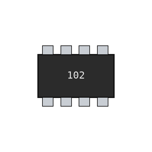 Red de resistencias de chip4 RN1-RN4
 Resistencia de chip2 1M
 Condensador cerámico de chip11 7x100n, 2x1u, 2x22p
 Varistor de chip2 Z1, Z2
 Perla de ferrita1 L1
 Inductor SMD1 L2
 Diodo SMD2 D2, D3
 LED de chip4 1 green, 3 yellow
 Alambre de soldadura1 a little
Herramientas necesarias:
 Fundente
 Pinzas de punta fina
 Estación de aire caliente para retrabajo
 Soldador de estañoLupa de relojero
3
3
Fit the power and chip parts
Fit the power and chip parts
Solder the ATmega16U2 (U3), the 16 MHz resonator Y2 and crystal Y1, the 5 V regulator NCP1117 (U1) and 3.3 V regulator LP2985 (U2), the LMV358 op-amp (U5), the FDN340P transistor (T1), the M7 diode (D1), the 500 mA resettable fuse (F1) and the 47 uF capacitors PC1, PC2 with their polarity as marked.
Materiales para este paso:
 Microcontrolador ATmega16U21 U3
 Resonador cerámico piezoeléctrico1 Y2
 Cristal de cuarzo1 Y1
 Regulador de tensión lineal2 U1 5 V, U2 3.3 V
 Circuito integrado amplificador operacional1 U5 LMV358
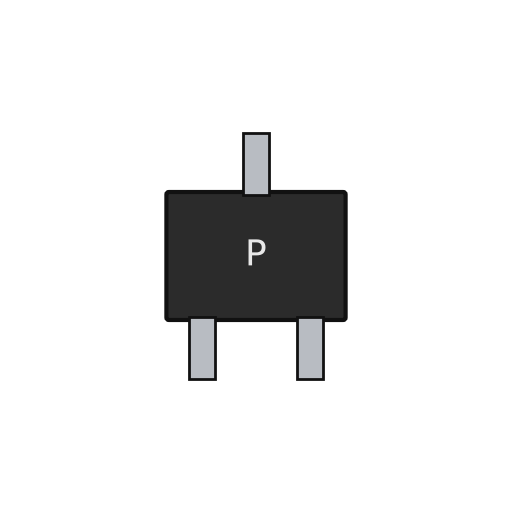 MOSFET de canal P1 T1Diodo SMD1 D1 M7
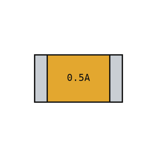 Fusible rearmable1 F1
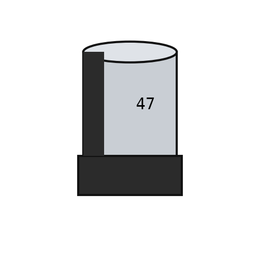 Condensador de chip polarizado2 PC1, PC2Alambre de soldadura1 a little
Herramientas necesarias:
FundentePinzas de punta finaEstación de aire caliente para retrabajoSoldador de estañoLupa de relojero4
4
Fit the through-hole parts
Fit the through-hole parts
Solder the USB-B socket (X2), the DC jack (X1), the reset switch, the female headers (one 10-way, two 8-way, one 6-way) and the two 2x3 ICSP headers. Seat the ATmega328P in its place (ZU4).
Materiales para este paso:
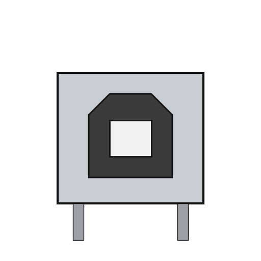 Conector USB-B1 X2
 Jack de alimentación1 X1
 Pulsador1 RESET
 Tira de pines6 10x1, 2x 8x1, 6x1 female; 2x 3x2 ICSP
 Microcontrolador ATmega328P1 ZU4Alambre de soldadura1 as needed
Herramientas necesarias:
Soldador de estaño5
5
Flash and check
Flash and check
Check with a meter that 5 V and GND are not shorted. Through the ICSP headers, load the USB-to-serial firmware into the ATmega16U2 and the bootloader into the ATmega328P. Plug in USB: the green ON LED lights, and the blink test in the next step flashes the L LED. Ours: an AVR ISP programmer and a multimeter.
Materiales para este paso:
 Firmware de Arduino Uno1 download
Herramientas necesarias:
 Multímetro
 Programador AVR ISP
 Cable USB-B
6
6
The blink test
The blink test
blink_test.ino: the same check as Arduino's Blink example. Upload it over USB from the Arduino IDE with the board set to Arduino Uno; the L LED on pin 13 turns on for one second and off for one second, over and over. If it does, both processors, the USB link and the bootloader work.
blink_test.inocpp
Herramientas necesarias:
Cable USB-BMateriales
24- 1 UNO-TH Rev3e layoutMarcador de posición
- 4 RN1-RN4Marcador de posición
- Marcador de posición
- 11 7x100n, 2x1u, 2x22pMarcador de posición
- 2 Z1, Z2Marcador de posición
- 1 L1Marcador de posición
- 1 L2Marcador de posición
- 1 D1 M7Marcador de posición
- 4 1 green, 3 yellowMarcador de posición
- 1 as neededMarcador de posición
- Marcador de posición
- Marcador de posición
- Marcador de posición
- 2 U1 5 V, U2 3.3 VMarcador de posición
- 1 U5 LMV358Marcador de posición
- Marcador de posición
- Marcador de posición
- 2 PC1, PC2Marcador de posición
- 1 X2Marcador de posición
- Marcador de posición
- Marcador de posición
- Marcador de posición
- Marcador de posición
- 1 downloadMarcador de posición
Herramientas requeridas
8- Marcador de posición
- Marcador de posición
- Marcador de posición
- Marcador de posición
- 2 vendors sell this, none ship to you yetMarcador de posición
- Marcador de posición
- Marcador de posición
- 1 vendor sell this, none ship to you yetMarcador de posición
Este plano hace
Blueprints relacionados
Estos blueprints comparten conocimiento — técnicas, materiales o principios
CC0 Dominio público
Este Blueprint se publica bajo CC0. Eres libre de copiar, modificar, distribuir y usar este trabajo para cualquier propósito, sin pedir permiso.
Apoya al Maker comprando productos a través de su Blueprint, donde gana una Comisión del Maker establecida por los vendedores, o crea una nueva iteración de este Blueprint e inclúyela como conexión en tu propio Blueprint para compartir ingresos.