Colaboración
ARTE
BELLEZA Y BIENESTAR
ARTESANÍA
CULTURA E HISTORIA
ENTRETENIMIENTO
MEDIO AMBIENTE
COMIDA Y BEBIDAS
INGENIERÍA INVERSA
CIENCIAS
DEPORTES
TECNOLOGÍA
TECNOLOGÍA VESTIBLE
Toggle-Lever Churn: A Crank Crooks and Straightens a Jointed Lever, Rocking a Walking Beam Twice Each Turn
Buttercup

Creado por

Buttercup

11. noviembre 2026IE
0
0
0
0
0

Toggle-Lever Churn: A Crank Crooks and Straightens a Jointed Lever, Rocking a Walking Beam Twice Each Turn

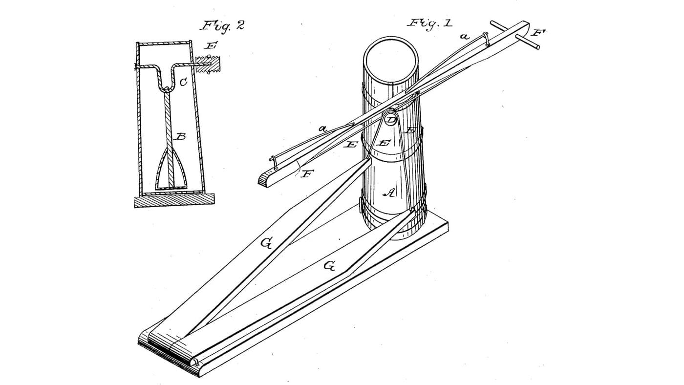
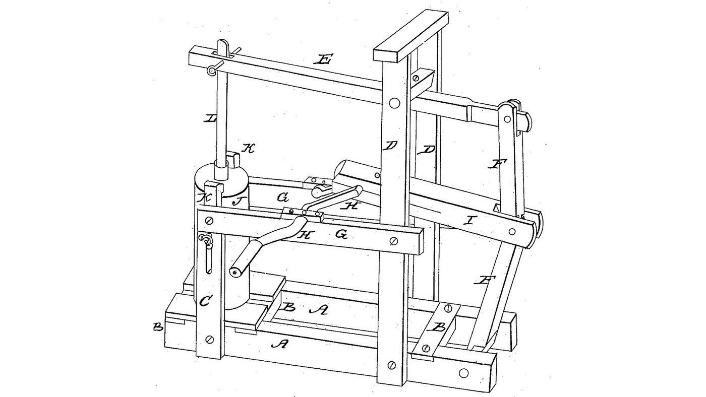
Edwin B. Clement of Barnet, Vermont, received US 27,205, dated 21 February 1860, for a churn. A walking beam on tall posts carries the dasher staff at one end; its other end is joined to a toggle-jointed lever standing on a shaft in the ends of the sills. A crank pushes and pulls the toggle's knee, crooking and straightening it, so the dasher goes "up and down twice to one revolution of the crank". The patent gives no sizes; every size here is ours.
Avanzado
About 3 days, plus printing

Instrucciones

1

Two strokes to one turn

Cargando el cuaderno de Jupyter…
2

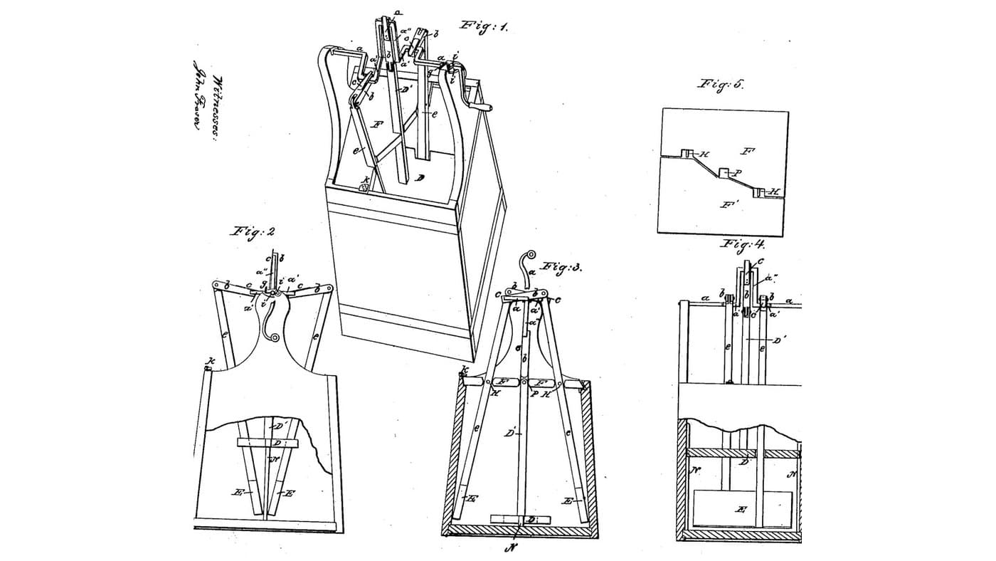
A crank that strokes a dasher, the year before

Austin's crank strokes the dasher once a turn. Clement's toggle gives two strokes a turn.
3

A crank-driven dasher, one week before

Willson turns his dasher's crank with a bow. Clement keeps the hand crank and adds a beam and toggle.
4

Read US 27,205

"One end of the walking beam is connected with a toggle jointed lever, the lower end of which lever is connected with a shaft that turns or rocks in the ends of the sills A, A, see letter F F." ... "I now come to the operation, which is simply to turn the crank H, which will alternately crook and straighten the toggle jointed lever causing the dasher to move up and down twice to one revolution of the crank."
5

Print the dasher

Cone dasher 160 mm across, open underneath, with a socket 22.6 mm across for the dasher staff. PETG, 0.2 mm layers, 40 % infill, 4 walls.
Archivo de DisenoSTLCC0 - Free
6

Frame: sills A, cross ties B, posts C and D

From pine lumber cut two sills 80 x 100 mm, 1250 mm long, and lay them 400 mm apart, centre to centre. Let three cross ties 80 x 30 mm into their tops: one under the churn's place near one end, one in the middle, one 100 mm in from the far end. Screw a board 340 x 300 mm on the end tie, between the sills, for the churn to stand on. Let two posts C, 60 x 60 mm, into the sills either side of the churn's place, reaching 560 mm above the floor, and two posts D 650 mm along from them, reaching 760 mm. Bore the posts D 17 mm across, 650 mm above the floor, for the beam's pivot, and the sills' far ends 21 mm across, 60 mm above the floor and 50 mm from the ends, for the rocking shaft.

Materiales para este paso:

Madera de pinoMadera de pino4 piezas
Tabla de madera duraTabla de madera dura1 pieza
Tornillos para maderaTornillos para madera40 piezas
Cola de carpinteroCola de carpintero1 pieza

Herramientas necesarias:

Sierra de mesaSierra de mesa
Taladro inalámbricoTaladro inalámbrico
Juego de brocasJuego de brocas
Juego de brocas de palaJuego de brocas de pala
SargentoSargento
Juego de destornilladoresJuego de destornilladores
Cinta métricaCinta métrica
7

Walking beam E and dasher staff L

Cut a hardwood beam 40 x 60 mm, 1010 mm long. Cut a slot 28 x 80 mm through it 30 mm from one end for the staff, and bore 12.8 mm across that slot. Bore 16.8 mm across 650 mm from the slot's centre for a 16 mm stainless pivot through the posts D, and 12.8 mm across 300 mm beyond the pivot for the toggle's pin. Glue a 22 mm hardwood staff into the dasher's socket so its top is 459 mm above the dasher's underside, and bore it 12.8 mm across 414 mm up from the underside; pin it in the beam's slot with a 12 mm stainless pin and split pins.

Materiales para este paso:

Tabla de madera duraTabla de madera dura1 pieza
Espigas de madera duraEspigas de madera dura1 pieza
Cola de carpinteroCola de carpintero1 pieza
Varilla de acero inoxidableVarilla de acero inoxidable1 pieza
Shaft CollarShaft Collar2 piezas
Pasador de aletasPasador de aletas2 piezas
Filamento PETGFilamento PETG1 pieza

Herramientas necesarias:

Impresora 3D de filamento (FDM)Impresora 3D de filamento (FDM)
Sierra de mesaSierra de mesa
Sierra de calarSierra de calar
Taladro inalámbricoTaladro inalámbrico
Juego de brocasJuego de brocas
Sierra para metalesSierra para metales
Limas (lima de mano)Limas (lima de mano)
Papel de lijaPapel de lija
8

Toggle-jointed lever F and rocking shaft

Pass a 20 mm stainless rod through the sills' far ends as the rocking shaft. Cut four hardwood links 15 x 40 mm, each with two 12.8 mm holes 320 mm apart: a pair of lower links on the rocking shaft, and a pair of upper links on the beam's end pin, either side of the beam. Join the four at the knee with one 12 mm stainless pin, the upper pair inside the lower pair, leaving the middle free for the connecting shaft. Secure every pin with split pins.

Materiales para este paso:

Varilla de acero inoxidableVarilla de acero inoxidable1 pieza
Tabla de madera duraTabla de madera dura1 pieza
Shaft CollarShaft Collar2 piezas
Pasador de aletasPasador de aletas6 piezas

Herramientas necesarias:

Sierra de mesaSierra de mesa
Taladro inalámbricoTaladro inalámbrico
Juego de brocasJuego de brocas
Sierra para metalesSierra para metales
Limas (lima de mano)Limas (lima de mano)
Tornillo de bancoTornillo de banco
Papel de lijaPapel de lija
9

Bars G, crank H and connecting shaft I

Screw a hardwood bar G 25 x 60 mm along the outside of each side, from post C to post D, 400 mm above the floor, and bore both 20.8 mm across 378 mm from the posts C. Cut a 20 mm stainless crank shaft 610 mm long, through both bars and 85 mm beyond one. Build the crank in the middle: two hardwood webs 30 x 14 mm, glued and pinned to the shaft with a 32 mm gap, carrying a 12 mm stainless crank pin 150 mm out; cut the shaft away between them. Outside the bar fit a hardwood arm 130 mm long with a dowel handle. Cut a hardwood connecting shaft I 30 x 40 mm with 12.8 mm holes 600 mm apart, from the crank pin to the knee pin. Fit collars either side of the bars.

Materiales para este paso:

Tabla de madera duraTabla de madera dura2 piezas
Varilla de acero inoxidableVarilla de acero inoxidable1 pieza
Espigas de madera duraEspigas de madera dura1 pieza
Cola de carpinteroCola de carpintero1 pieza
Tornillos para maderaTornillos para madera8 piezas
Shaft CollarShaft Collar2 piezas
Pasador de aletasPasador de aletas2 piezas

Herramientas necesarias:

Sierra de mesaSierra de mesa
Taladro inalámbricoTaladro inalámbrico
Juego de brocasJuego de brocas
Juego de brocas de palaJuego de brocas de pala
Sierra para metalesSierra para metales
Limas (lima de mano)Limas (lima de mano)
Tornillo de bancoTornillo de banco
SargentoSargento
Juego de destornilladoresJuego de destornilladores
10

Churn J and hooks K

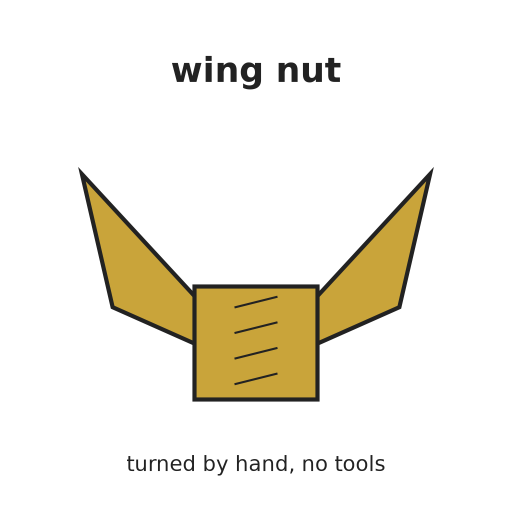
Bore a 48 mm hole in the centre of the bucket's lid for the staff. Bend two hooks from mild steel flat bar to reach from the posts C over the bucket's rim, and fasten each to its post with a carriage bolt and wing nut, as the patent's hooks are "provided each with a bolt and nut and fastened to the posts C".

Materiales para este paso:

Cubo de 20 litrosCubo de 20 litros1 pieza
Pletina de acero dulcePletina de acero dulce1 pieza
Tornillo de carruajeTornillo de carruaje2 piezas
Tuerca mariposaTuerca mariposa2 piezas

Herramientas necesarias:

Taladro inalámbricoTaladro inalámbrico
Juego de brocasJuego de brocas
Juego de brocas de palaJuego de brocas de pala
Sierra para metalesSierra para metales
Tornillo de bancoTornillo de banco
Limas (lima de mano)Limas (lima de mano)
Llave inglesa ajustableLlave inglesa ajustable
11

The build in 3D

FreeCAD model of this build, the churn cut through the middle: the sills, ties and posts, the walking beam on the posts D, the dasher staff, the toggle-jointed lever on the rocking shaft, the crank in the bars G and the connecting shaft to the toggle's knee.
Archivo de DisenoBLENDCC0 - Free
12

Churn

Lift the beam's dasher end, stand the bucket on its board with about 10 litres of heavy cream at about 15 °C, checked with the thermometer, lower the dasher in, put on the lid over the staff and fasten the hooks. Turn the crank steadily, timing it. When the butter comes, unhook the bucket, lift the dasher out, pour off the buttermilk into a bowl, wash the butter in cold water until it runs clear, salt and weigh it.

Materiales para este paso:

Crema de leche espesaCrema de leche espesa10 l
Sal marina gruesaSal marina gruesa1 pieza
AguaAgua1 pieza

Herramientas necesarias:

Termómetro de sonda permanenteTermómetro de sonda permanente
CronómetroCronómetro
Báscula digital de cocinaBáscula digital de cocina
Bol grande de acero inoxidableBol grande de acero inoxidable
13

Troubleshooting

Toggle-lever churn troubleshooting.

Flow

Loading...
14

History and honest limits

**Edwin B. Clement** of Barnet, Caledonia County, Vermont, US 27,205, 21 February 1860, "Churn". He claimed "the arrangement of the toggle joint F, walking beam E, crank H, and connecting shaft I". The patent gives no sizes and does not show one post C; every size here is ours, as are the bucket, the cone dasher, the paired links and the built-up crank.

Materiales

16

Herramientas requeridas

18

Archivos de diseño

2

CC0 Dominio público

Este Blueprint se publica bajo CC0. Eres libre de copiar, modificar, distribuir y usar este trabajo para cualquier propósito, sin pedir permiso.

Apoya al Maker comprando productos a través de su Blueprint, donde gana una Comisión del Maker establecida por los vendedores, o crea una nueva iteración de este Blueprint e inclúyela como conexión en tu propio Blueprint para compartir ingresos.

Discusión

(0)

Iniciar sesión para unirte a la discusión

Cargando comentarios...