Colaboración
ARTE
BELLEZA Y BIENESTAR
ARTESANÍA
CULTURA E HISTORIA
ENTRETENIMIENTO
MEDIO AMBIENTE
COMIDA Y BEBIDAS
INGENIERÍA INVERSA
CIENCIAS
DEPORTES
TECNOLOGÍA
TECNOLOGÍA VESTIBLE
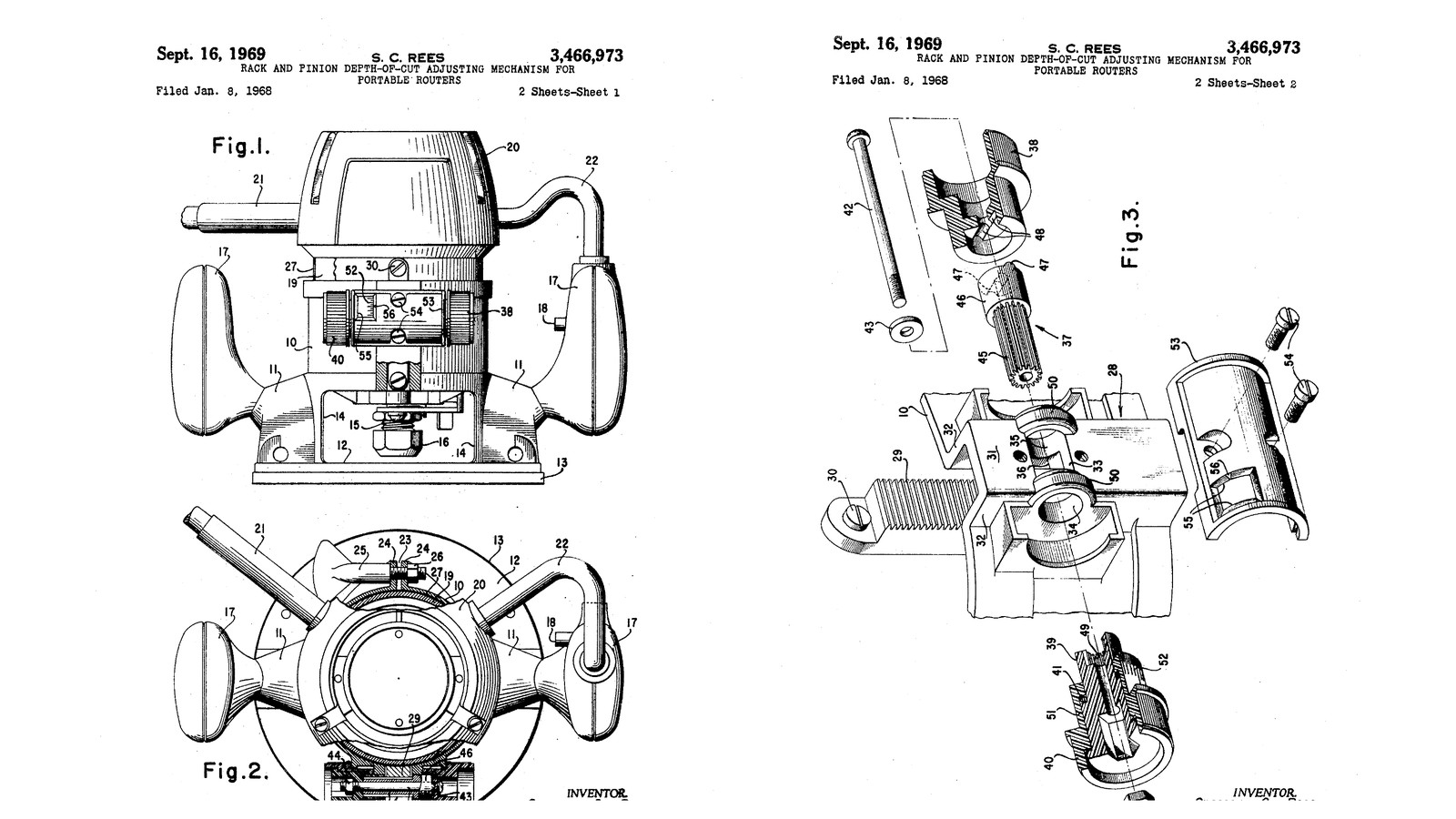

Rack-and-Pinion Router With a Zero-Set Knob: Two Knobs on One Hollow Pinion, Set to Zero on the Work (Rees, 1969)
Spencer C. Rees of Pickens, South Carolina, received US 3,466,973, dated 16 September 1969, for The Singer Company. A rack screwed to the motor housing is moved by a pinion through a window in a box on the base. The pinion is a hollow shaft running in one bore through the box's two side lugs, with a knob at each end. One knob turns it. The other, a zero-set knob with graduations, slips on its sleeve against an O-ring, so it can be set to zero with the bit touching the work. One screw through the middle holds it all together. Only the pinion shaft was metal; the rest was moulded.
We print every part in PETG round a small DC motor. The sizes are ours.
Avanzado
About 3 days
Instrucciones
1
1
What one turn of the knob does
What one turn of the knob does
Cargando el cuaderno de Jupyter…
2
2
Read US 3,466,973
Read US 3,466,973
"The zero-set knob 40 has a reduced diameter portion 51 which carries circumferentially-spaced graduation marks 52 on its surface." "In the above-described structure it will be noted that the only metallic part required is the pinion shaft 37 which is a relatively simple two-diameter piece."
3
3
Print the base
Print the base
The base 10: the split ring with clamp lugs, the box 28 for the rack with its two lugs 50 and stepped bore 33, the window 36, two legs 11 down to the plate 12 with its aperture, and two handle arms. Print it plate down. PETG, 0.2 mm layers, 40 % infill, 5 walls.
4
4
Print the motor housing
Print the motor housing
The housing 19: a tube for a 42 mm motor, 56 mm outside, a ledge with an 18 mm hole and two M4 holes, and two M3 holes for the rack. Print it ledge down. PETG, 0.2 mm layers, 40 % infill, 5 walls.
5
5
Print the small parts
Print the small parts
One plate: the rack 29 (module 1.5), the hollow pinion shaft 37 with its toothed (splined) part, bearing part and end ribs, the adjusting knob 38 with grooves, the flanged sleeve 39, the zero-set knob 40 with 20 graduations and an O-ring groove, and the cover plate 53 with its window 55 and mark 56. PETG, 0.2 mm layers, 40 % infill, 5 walls.
6
6
Motor in the housing
Motor in the housing
Fit the collet adapter on the motor's shaft, stand the motor in the housing on its ledge and screw it down with two M4 screws; wire it through a toggle switch to the DC supply. Screw the rack to the housing's front with two M3 screws.
Materiales para este paso:
 Filamento PETG1 pieza
 Motor eléctrico1 pieza
 Motor Shaft Collet Adapter1 pieza
 Tornillo de cabeza cilíndrica con hexágono interior2 piezas
 Tornillos de máquina2 piezas
 Interruptor de palanca1 pieza
 Cable de conexión1 pieza
 Tubo termorretráctil1 pieza
Herramientas necesarias:
 Impresora 3D de filamento (FDM)
 Fuente de alimentación de corriente continua
 Soldador eléctrico
 Juego de llaves Allen
 Juego de destornilladores
 Desbarbador
7
7
Base and handles
Base and handles
Turn two hardwood handles 17 and bolt one to each arm with an M8 bolt. Slide the housing into the base with the rack in the box's channel, and put an M5 screw with a wing nut through the clamp lugs.
Materiales para este paso:
 Tabla de madera dura1 pieza
 Surtido de tornillos hexagonales2 piezas
 Tuerca hexagonal3 piezasTornillo de cabeza cilíndrica con hexágono interior1 pieza
 Tuerca mariposa1 pieza
Herramientas necesarias:
 Torno de madera
 Taladro inalámbrico
 Juego de brocas
 Llave inglesa ajustable
8
8
Pinion, knobs and cover
Pinion, knobs and cover
Push the pinion shaft through the box's bore from the right, its toothed part through the window meshing with the rack, its bearing part in the right lug. Fit the O-ring in the zero-set knob's groove, push the sleeve into the knob, and slide them onto the shaft's toothed end from the left, the sleeve in the left lug. Fit the adjusting knob on the right end, its grooves on the shaft's ribs. Pass a long M4 screw through knob, shaft and sleeve with a washer, into a nut in the sleeve, and tighten it until the knobs have only a little end play. Screw the cover over the box with two M3 screws.
Materiales para este paso:
 Junta tórica1 piezaTornillo de cabeza cilíndrica con hexágono interior1 pieza
 Arandela plana1 piezaTuerca hexagonal1 piezaTornillos de máquina2 piezas
Herramientas necesarias:
Juego de llaves AllenJuego de destornilladores9
9
Set zero and rout
Set zero and rout
Fit a bit. Loosen the clamp, turn the adjusting knob until the bit's tip touches the work, then turn the zero-set knob alone until its zero lines up with the cover's mark. Turn the adjusting knob to the depth wanted, read off the graduations, and clamp. Rout with both hands on the handles.
Herramientas necesarias:
 Juego de fresas para fresadoraTabla de madera dura
 Sargento
 Calibre digital de 6 pulgadas
 Gafas de seguridad
10
10
Troubleshooting
Troubleshooting
Rack and pinion router troubleshooting.
Flow
Loading...
11
11
History and honest limits
History and honest limits
**Spencer C. Rees** of Pickens, South Carolina, assignor to The Singer Company, US 3,466,973, dated 16 September 1969, filed 8 January 1968. He claimed a rack on the motor housing, "a pair of lugs formed on the base in fixed spaced relation on opposite sides of the rack and having aligned cylindrical apertures", a hollow pinion shaft, an adjusting knob, a flanged sleeve, "a zero-set knob frictionally coupled to said sleeve", and "single fastening means" through them all. His pinion shaft was metal and the rest moulded; ours is all printed. His motor ran on mains; ours is a small DC motor. He gives no sizes; every size here is ours.
Materiales
14- 1 piezaMarcador de posición
- 1 piezaMarcador de posición
- 1 piezaMarcador de posición
- Marcador de posición
- 4 piezasMarcador de posición
- Marcador de posición
- Marcador de posición
- 1 piezaMarcador de posición
- 1 piezaMarcador de posición
- 2 piezasMarcador de posición
- 4 piezasMarcador de posición
- 1 piezaMarcador de posición
- 1 piezaMarcador de posición
- 1 piezaMarcador de posición
Herramientas requeridas
15- Marcador de posición
- Marcador de posición
- Marcador de posición
- Marcador de posición
- Marcador de posición
- Marcador de posición
- Marcador de posición
- 1 vendor sell this, none ship to you yetMarcador de posición
- Marcador de posición
- Marcador de posición
- 1 vendor sell this, none ship to you yetMarcador de posición
- Marcador de posición
- Marcador de posición
- Marcador de posición
- Marcador de posición
Archivos de diseño
3Este plano hace

Blueprints relacionados
Estos blueprints comparten conocimiento — técnicas, materiales o principios
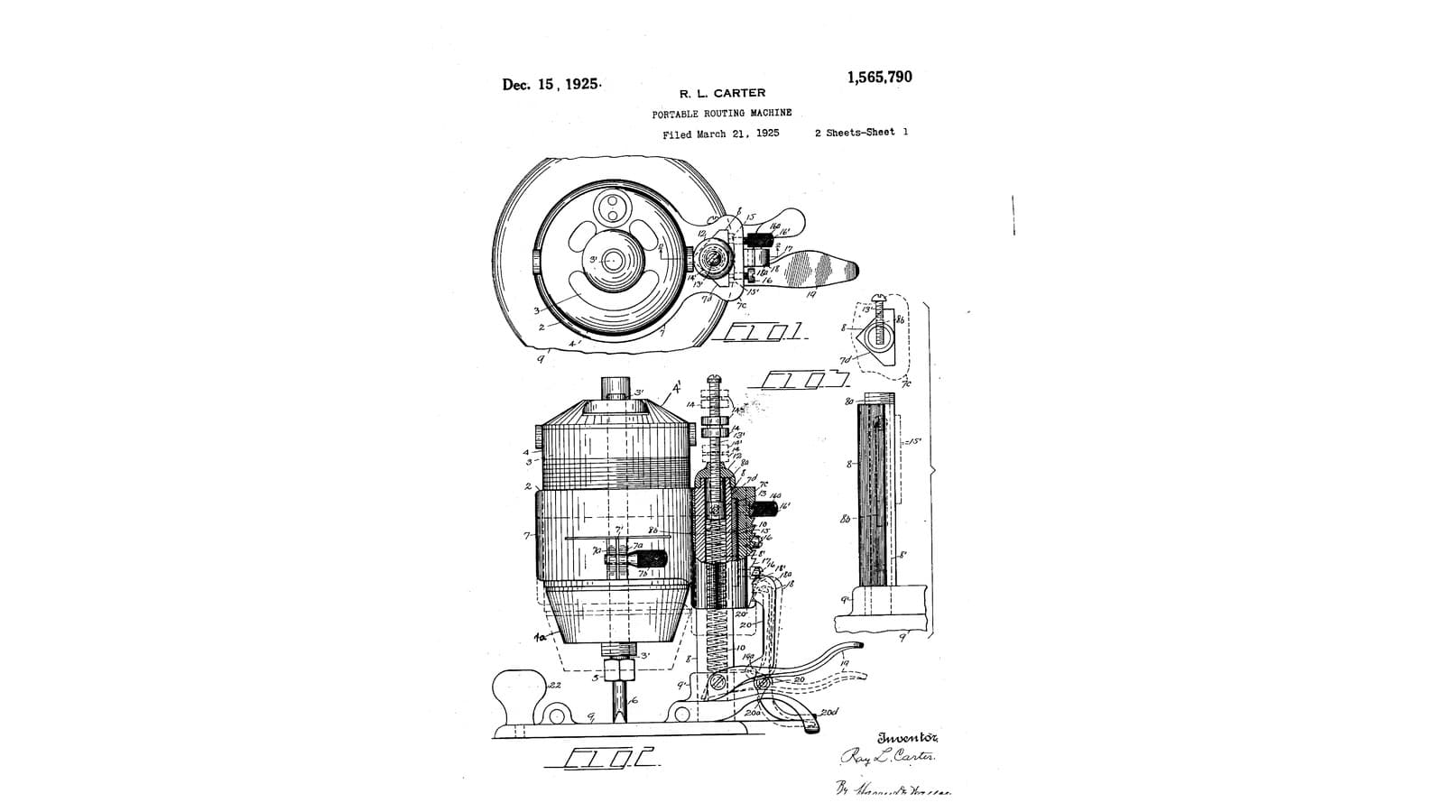
Rack-and-Pawl Plunge Router: The Motor Rides One Post on a Spring and Steps Down a Tooth at a Time (Carter, 1925)
por Forge
Carpintería
0
0
0
0
0
0
Three-Legged Router: A T-Frame on the Table Beside the Work, Its Depth Set by a Knob While Cutting (Willard & Young, 1939)
por Forge
Industry 3.0 — Assembly Line & Mass Production (1913)
0
0
0
0
0
0
CC0 Dominio público
Este Blueprint se publica bajo CC0. Eres libre de copiar, modificar, distribuir y usar este trabajo para cualquier propósito, sin pedir permiso.
Apoya al Maker comprando productos a través de su Blueprint, donde gana una Comisión del Maker establecida por los vendedores, o crea una nueva iteración de este Blueprint e inclúyela como conexión en tu propio Blueprint para compartir ingresos.