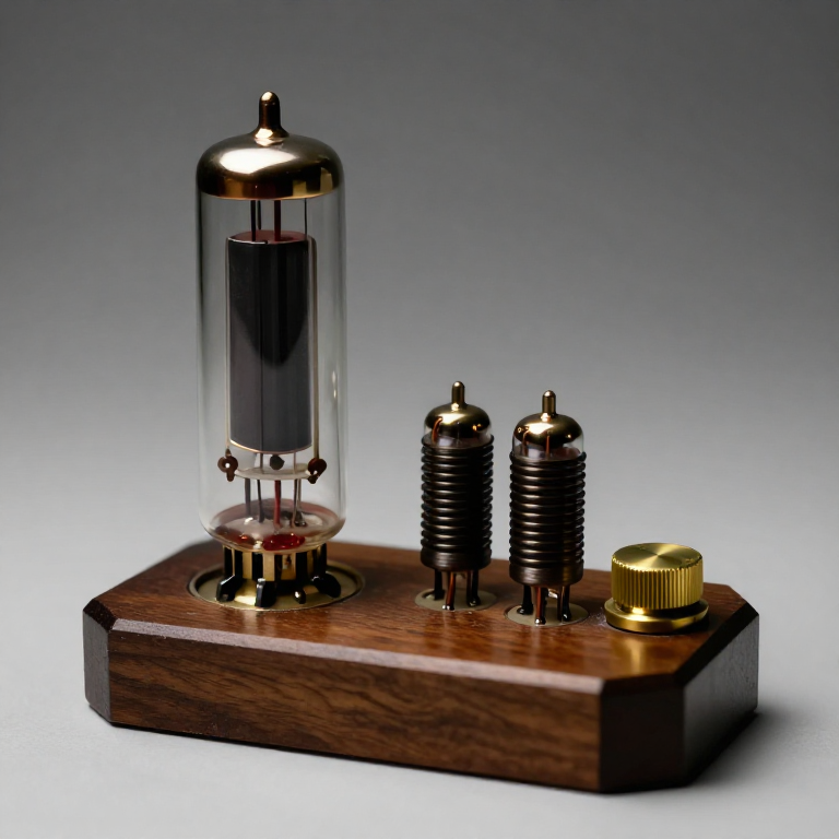


The Regenerative Receiver
Instrucciones
Measure the gain of one stage without feedback
Measure the gain of one stage without feedback
Establish the baseline the trick has to beat.
- Build a single amplifying stage — a triode valve, or a JFET if you prefer to work at low voltage — with your tuned circuit as its input load.
- Inject a small known signal and measure the output amplitude.
- Compute the voltage gain.
- Measure the bandwidth of the stage as you did for the bare tuned circuit.
One stage gives perhaps twenty to fifty times, and the tuned circuit’s Q is slightly WORSE than it was standalone. That degradation is the important observation: the valve’s input is not infinitely light, and whatever it loads onto the tuned circuit costs you selectivity.
Valve circuits run at voltages that will hurt you — often 150 V and up. Discharge every capacitor before touching anything, keep one hand in a pocket while probing, and never work on a live chassis. If you would rather not, the JFET version of this blueprint demonstrates identical behaviour at 12 V and is genuinely equivalent for everything that follows.Materiales para este paso:
 Válvula triodo1 piezaVálvula triodo1 juego
 Zócalo de válvula1 juego
 Juego de resistencias1 kit
 Kit de condensadores1 kit
 Placa perforada / placa de prototipos1 pieza
 Alambre de soldadura1 reel
Herramientas necesarias:
 Osciloscopio
 Generador de señales
 Multímetro digital de laboratorio
 Fuente de alimentación de banco ajustable
 Estación de soldadura
 Analizador de espectro / software FFT
 Gafas de seguridad transparentes
Add the tickler coil and find the threshold
Add the tickler coil and find the threshold
Feed a little of the output back into the input, in phase, and increase it slowly.
- Wind a small coil — the tickler — near the main tuned coil, connected in the output circuit.
- Arrange a way to vary the coupling: physically move the tickler, or use a potentiometer to control how much output reaches it.
- With a weak test signal applied, increase the feedback gradually while watching the output.
- Record output amplitude against feedback setting.
Gain climbs slowly at first, then accelerates dramatically, and just before it becomes unstable it is enormous. The circuit is now supplying part of its own losses: each cycle is reinforced by the amplified version of the previous cycle, so the ringing you saw decay in the tuned-circuit blueprint decays far more slowly.
If the tickler is connected the wrong way round you will get NEGATIVE feedback instead — gain falls below the plain amplifier. Reverse the coil. That accident is worth having deliberately, because it demonstrates that the sign of the feedback is everything and the magnitude is only the fine adjustment.
Reverse-engineering note: the tickler was often wound directly over the main coil on the same former, with its position adjustable by a lever on the front panel. That mechanical adjustment IS the regeneration control, and on period receivers it is usually the knob marked simply “REGEN”.Materiales para este paso:
 Hilo de cobre esmaltado10 m
 Potenciómetro1 piezaKit de condensadores1 kit
 Formador de plástico1 pieza
Herramientas necesarias:
OsciloscopioGenerador de señalesMultímetro digital de laboratorioFuente de alimentación de banco ajustableEstación de soldadura Medidor LCR de sobremesaGafas de seguridad transparentes
Cross the threshold on purpose and get an oscillator
Cross the threshold on purpose and get an oscillator
Push the feedback past the point of stability and see what the circuit becomes.
- Remove the input signal entirely.
- Advance the regeneration control past the threshold.
- Look at the output on the oscilloscope and measure its frequency.
- Compare that frequency with the tuned circuit’s resonance measured earlier.
With no input at all, the circuit produces a clean sine wave at its resonant frequency. It has become an oscillator. Feedback greater than the losses means any tiny disturbance — thermal noise, switch-on transient — is amplified, fed back, amplified again, and grows until the valve runs out of linear range and the amplitude settles.
This is the single most important boundary in electronics: an amplifier and an oscillator are the same circuit, separated only by how much of the output returns to the input. Every oscillator is built by deliberately crossing this line; every amplifier that squeals or a PA system that howls has crossed it by accident. The Barkhausen condition — loop gain of one, phase shift of zero — is just this observation written down.
An oscillating regenerative receiver also RADIATES from its antenna, turning it into a small transmitter that interferes with neighbours. This was a genuine nuisance in the 1920s and is why the superheterodyne, which keeps its oscillator away from the antenna, eventually replaced it in domestic sets.Materiales para este paso:
Kit de condensadores1 kitJuego de resistencias1 kitHerramientas necesarias:
OsciloscopioAnalizador de espectro / software FFTMultímetro digital de laboratorioFuente de alimentación de banco ajustableGafas de seguridad transparentesSit just below oscillation and receive AM
Sit just below oscillation and receive AM
The useful operating point is a hair below the threshold, and finding it is a skill.
- Connect antenna and earth, and a high-impedance earpiece or an audio amplifier at the output.
- Tune to a station, then advance regeneration slowly until you hear the background noise rise sharply and the signal strengthen.
- Back off very slightly, until just before the circuit whistles.
- Re-measure the effective bandwidth by sweeping a test signal at this setting.
Sensitivity and selectivity are both dramatically better than the crystal set — often by orders of magnitude — from one valve. The bandwidth at this operating point is a small fraction of what the same tuned circuit gave passively, because the feedback is cancelling the resistance that was broadening it.
Notice how touchy the control is, and how it drifts as the valve warms. Adjusting regeneration is a continuous manual activity on these receivers, and a strong signal can push the circuit into oscillation by itself. This awkwardness is the honest price of the design and is precisely why it was superseded — not because it worked badly, but because it demanded skill from the listener.Materiales para este paso:
Hilo de cobre esmaltado30 m Auricular de cristal (alta impedancia)1 pieza
 Condensador variable (dieléctrico de aire)1 piezaKit de condensadores1 kit
Herramientas necesarias:
OsciloscopioGenerador de señalesMultímetro digital de laboratorioFuente de alimentación de banco ajustableAnalizador de espectro / software FFTGafas de seguridad transparentesPush past oscillation deliberately, and receive Morse
Push past oscillation deliberately, and receive Morse
The state you were avoiding turns out to be exactly what a different signal needs.
- Tune to a continuous-wave Morse transmission — an unmodulated carrier that simply switches on and off.
- With regeneration below threshold, listen. You will hear almost nothing but clicks.
- Now advance past the threshold so the circuit oscillates, and tune slightly off the carrier frequency.
- Listen again, and vary the offset.
The Morse becomes a clear musical tone whose pitch you can set by how far off you tune. The local oscillation and the incoming carrier are mixing, and the difference between two frequencies is an audible beat note. A carrier that carries no modulation is silent by itself; heterodyning it against a local oscillator makes it audible.
Take that idea seriously, because it is the whole of the next blueprint. Mixing two frequencies produces their sum and their difference, and the difference can be placed anywhere you choose by choosing the local oscillator. Here it is used to move a signal down to audio. In the superheterodyne it is used to move any station to one fixed frequency, so a single perfectly-optimised amplifier can handle all of them.
Armstrong invented both, six years apart, from the same observation. The second is arguably the most reused idea in the history of electronics.Materiales para este paso:
Kit de condensadores1 kit Papel milimetrado1 pad
Herramientas necesarias:
OsciloscopioAnalizador de espectro / software FFTGenerador de señalesMultímetro digital de laboratorioGafas de seguridad transparentesMateriales
12- 1 juegoMarcador de posición
- 1 juegoMarcador de posición
- Marcador de posición
- 1 kitMarcador de posición
- Marcador de posición
- 1 reelMarcador de posición
- Marcador de posición
- Marcador de posición
- 1 piezaMarcador de posición
- Marcador de posición
- Marcador de posición
- 1 padMarcador de posición
Herramientas requeridas
8- Marcador de posición
- Marcador de posición
- Marcador de posición
- Marcador de posición
- Marcador de posición
- Marcador de posición
- Marcador de posición
- Marcador de posición
Blueprints relacionados
Estos blueprints comparten conocimiento — técnicas, materiales o principios

CC0 Dominio público
Este Blueprint se publica bajo CC0. Eres libre de copiar, modificar, distribuir y usar este trabajo para cualquier propósito, sin pedir permiso.
Apoya al Maker comprando productos a través de su Blueprint, donde gana una Comisión del Maker establecida por los vendedores, o crea una nueva iteración de este Blueprint e inclúyela como conexión en tu propio Blueprint para compartir ingresos.