ARTE
BELLEZA Y BIENESTAR
ARTESANÍA
CULTURA E HISTORIA
ENTRETENIMIENTO
MEDIO AMBIENTE
COMIDA Y BEBIDAS
INGENIERÍA INVERSA
CIENCIAS
DEPORTES
TECNOLOGÍA
TECNOLOGÍA VESTIBLE


The Hydrostatic Transmission: A Gearbox Made of Oil
A variable-displacement pump can send out anything from nothing to its full flow while its shaft turns steadily. Put a second axial-piston machine at the other end of the oil — running as a motor — and the pump's swash angle becomes a gear lever with no steps: forward, stop and reverse from one handwheel, with the engine never changing speed.
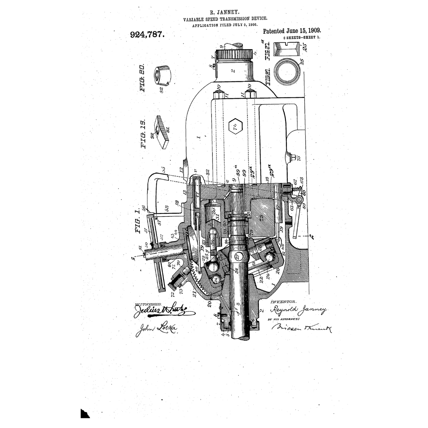
Reynold Janney of the Waterbury Tool Company, working with Harvey D. Williams, filed US 924,787, *Variable-Speed-Transmission Device*, on 9 July 1906; it was granted 15 June 1909. The driving and driven units share one mid-plate with two ports, one for oil going out and one for its return, and a handwheel and scroll tilt the driving unit's swash ring.
This rung works out the speed and torque ratios and the efficiency, and builds a syringe model in which moving one pin changes the ratio from zero to full.
Intermedio
About 4 hours
Instrucciones
1
1
Ratio, reversal and efficiency
Ratio, reversal and efficiency
Cargando el cuaderno de Jupyter…
2
2
The pump half
The pump half
The driving half of the transmission is Janney's variable-displacement pump. The embedded blueprint shows how tilting the swash ring changes the pistons' stroke.
3
3
Read the mid-plate from the patent
Read the mid-plate from the patent
Sheet 1 of US 924,787 shows the whole machine in section: two cylindrical casings bolted either side of a mid-plate 13, a cylinder barrel 29 turning against each face of it, and pistons 31 driven by rods 34 from a socket ring 23 on a tilting box 20.
The specification's key points: the mid-plate's two ports are extended into tapering V-shaped channels "for the purpose of securing a more gradual opening and closing" as each cylinder port passes them — the same trick used in every axial-piston machine since to stop a pressure shock at each piston. Turning handwheel 51 turns a scroll disk that tilts the box; "when the race 22 is perpendicular to the shaft, the pistons 31 will not move at all in the cylinders 30, and the barrel 29 will rotate idly. The greater the inclination of the race 22, the longer will be the stroke of the pistons 31, and the greater therefore the speed of the driven member." Oil drilled through the pistons and rods lubricates both ball ends.
4
4
Build a variable-stroke syringe drive
Build a variable-stroke syringe drive
Screw a plywood disc 120 mm across to the output shaft of a geared DC motor, and drill a row of holes along one radius at 0, 10, 20, 30 and 40 mm from the centre. A pin in one of the holes drives a connecting rod to the plunger of a 20 mL syringe: that is the pump, and the hole you choose is its swash angle.
Join its tip with a short, stiff tube to a second 20 mL syringe mounted along a steel rule: that is the motor, and its plunger's travel is the output. Fill both with water and bleed out all the air.
Run the motor at a steady speed and measure the output stroke with the pin in each hole. It rises in proportion to the pin radius, and with the pin at the centre the input turns and the output stands still. Change the output syringe for a smaller one: its stroke grows by the ratio of the areas — the motor's displacement sets the ratio too.
Materiales para este paso:
 Juego de jeringas1 pieza
 Tubo de silicona1 metro
 Tablero contrachapado1 pieza
 Tornillos de máquina6 piezas
 Motorreductor de corriente continua1 pieza
 Agua1 litro
Herramientas necesarias:
 Fuente de alimentación de corriente continua
 Taladro inalámbrico
 Juego de brocas
 Regla
 Calibre digital de 6 pulgadas
 Cronómetro
5
5
A hydrostatic drive that loses its way
A hydrostatic drive that loses its way
Hydrostatic drive faults and where they point.
Flow
Loading...
6
6
History and context
History and context
**Reynold Janney**, of New York, assignor to the **Waterbury Tool Company** of Waterbury, Connecticut, filed **US 924,787** on 9 July 1906; granted 15 June 1909. With **Harvey D. Williams** he developed the Williams–Janney variable speed gear, among the first hydraulic machines to run on oil rather than water. The US Navy used Waterbury gears to train and elevate gun turrets, and a Williams–Janney gear built in England is in the Science Museum Group collection.
Hydrostatic drives now move combine harvesters, skid-steer loaders, lawn tractors and winches.
**Honest limits.** The notebook's efficiencies are typical figures, not Janney's: real losses depend on speed, pressure and oil viscosity. A closed loop heats its own oil and needs a charge pump and cooling, which the syringe model cannot show.
Materiales
6- 1 piezaMarcador de posición
- 1 metroMarcador de posición
- 1 piezaMarcador de posición
- 6 piezasMarcador de posición
- Marcador de posición
- 1 litroMarcador de posición
Herramientas requeridas
6- Marcador de posición
- 1 vendor sell this, none ship to you yetMarcador de posición
- Marcador de posición
- Marcador de posición
- Marcador de posición
- Marcador de posición
Blueprints relacionados
Estos blueprints comparten conocimiento — técnicas, materiales o principios

CC0 Dominio público
Este Blueprint se publica bajo CC0. Eres libre de copiar, modificar, distribuir y usar este trabajo para cualquier propósito, sin pedir permiso.
Apoya al Maker comprando productos a través de su Blueprint, donde gana una Comisión del Maker establecida por los vendedores, o crea una nueva iteración de este Blueprint e inclúyela como conexión en tu propio Blueprint para compartir ingresos.