
Colaboración
ARTE
BELLEZA Y BIENESTAR
ARTESANÍA
CULTURA E HISTORIA
ENTRETENIMIENTO
MEDIO AMBIENTE
COMIDA Y BEBIDAS
INGENIERÍA INVERSA
CIENCIAS
DEPORTES
TECNOLOGÍA
TECNOLOGÍA VESTIBLE
Sprung-Leg Tubing Cutter: a Bent Rod With a Disk Outside and a Roller Inside, the Handle's Screw Bends One Leg In (Zeiler, 1958)
Forge

Creado por

Forge

13. noviembre 2026NO
0
0
0
0
0

Sprung-Leg Tubing Cutter: a Bent Rod With a Disk Outside and a Roller Inside, the Handle's Screw Bends One Leg In (Zeiler, 1958)

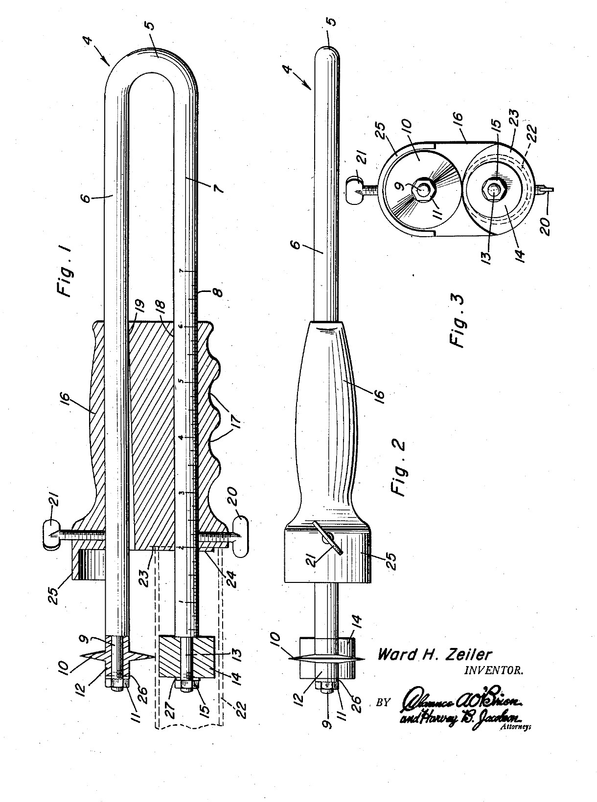
Ward H. Zeiler of Holyoke, Colorado, received US 2,821,781, dated 4 February 1958, for a plumber's tubing cutter that cuts a tube square, to length, near its end. The frame is one springy rod bent into a U. The lower leg goes into the tube and carries a roller. The upper leg carries a cutting disk outside the tube. A handle slides along both legs. Its front end stops against the tube end, so the cut length is read off a scale on the lower leg. A screw in the handle bends the upper leg in and presses the disk onto the tube, and turning the tool cuts it off. All sizes are ours.
Intermedio
About 2 days

Instrucciones

1

Why the frame must spring

Cargando el cuaderno de Jupyter…
2

Read US 2,821,781

"The leg 7 is then inserted in the tube 22 and the roller 14 and the projection 24 are engaged in the upper portion of said tube. The screw 21 is then tightened for bending the leg 6 of the frame 4, thus engaging the knife 10 with the periphery of the tube 22."
3

Print the template

The bent frame, its ends, the disk, roller and handle at 1:1, with the oval bore, the screws and the scale. print at 100 % (check the 50 mm bar).
Archivo de DisenoPDFCC0 - Free
4

Bend the frame

Cut 470 mm of 6 mm spring steel wire. Heat the middle 40 mm red with the torch and bend it round a 10 mm bar into a U with the legs 16 mm apart, and straighten the legs parallel. Heat the last 25 mm of each leg red and let it cool slowly in the dying forge, so the ends are soft enough to file and thread. Leave the rest of the legs as they are: they must spring.

Materiales para este paso:

Alambre de acero para muellesAlambre de acero para muelles1 pieza

Herramientas necesarias:
Soplete de soldadura fuerteSoplete de soldadura fuerte
FraguaFragua
Tenazas de fraguaTenazas de fragua
Tornillo de bancoTornillo de banco
Martillo de bolaMartillo de bola
Sierra para metalesSierra para metales
Guantes de soldadorGuantes de soldador
Gafas de seguridadGafas de seguridad
5

Thread the leg ends

Turn or file the last 24 mm of each leg to 5 mm, leaving a square shoulder, and cut an M5 thread on the last 8 mm with the die.

Herramientas necesarias:

Torno de metalTorno de metal
Plato de torno de 3 mordazasPlato de torno de 3 mordazas
Herramienta de corte para tornoHerramienta de corte para torno
Juego de limasJuego de limas
Juego de machos y terrajasJuego de machos y terrajas
Calibre digital de 6 pulgadasCalibre digital de 6 pulgadas
Aceite de corteAceite de corte
6

Turn the disk and the roller

Disk: chuck a tool steel bar, turn 12 mm of it to 18 mm, drill it 5 mm, and turn the front 6 mm to a 50 degree edge, sharp in its middle. Turn the next 4 mm down to a 10 mm hub and part it off. Roller: turn 10 mm mild steel bar 16 mm long and drill it 5.2 mm, so it spins freely on the leg.

Materiales para este paso:

Barra de acero de herramientasBarra de acero de herramientas1 pieza
Barra redonda de acero dulceBarra redonda de acero dulce1 pieza

Herramientas necesarias:

Torno de metalTorno de metal
Plato de torno de 3 mordazasPlato de torno de 3 mordazas
Herramienta de corte para tornoHerramienta de corte para torno
Gubia de tronzarGubia de tronzar
Juego de brocas de centrarJuego de brocas de centrar
Juego de brocasJuego de brocas
Calibre digital de 6 pulgadasCalibre digital de 6 pulgadas
Gafas de seguridadGafas de seguridad
7

Harden and temper

Heat the disk to a cherry red, until a magnet no longer sticks, and quench it in water, moving it about. Rub it bright with a stone, warm it on a piece of steel plate over the fire, and quench again as soon as it turns a light straw colour.

Herramientas necesarias:

FraguaFragua
Tenazas de fraguaTenazas de fragua
Imán pequeñoImán pequeño
Cubo de templeCubo de temple
AguaAgua
Piedra de afilarPiedra de afilar
Guantes de soldadorGuantes de soldador
Gafas de seguridadGafas de seguridad
8

Make the handle

Saw 90 mm of 32 mm aluminium bar and face the ends. Drill two 6.2 mm holes through it lengthways, 16 mm apart, each 8 mm off the centre. With a round file, open the front 70 mm of the upper hole towards the lower one, 1.8 mm at the front face, tapering to nothing. Drill and tap M6 into the upper hole from the top, 12 mm from the front, and into the lower hole from below, 14 mm from the front. Saw and file away the lower half of the front 8 mm, leaving a 10 mm round boss round the lower hole. File three finger grooves underneath.

Materiales para este paso:

Barra redonda de aluminioBarra redonda de aluminio1 pieza

Herramientas necesarias:

Sierra para metalesSierra para metales
Torno de metalTorno de metal
Plato de torno de 3 mordazasPlato de torno de 3 mordazas
Taladro de columnaTaladro de columna
Mordaza de máquinaMordaza de máquina
Juego de brocasJuego de brocas
Juego de machos y terrajasJuego de machos y terrajas
Juego de limasJuego de limas
Juego de limas de agujaJuego de limas de aguja
Calibre digital de 6 pulgadasCalibre digital de 6 pulgadas
9

Make the guard

Cut a strip of brass sheet 12 mm wide and 50 mm long, bend it into a half round hood that reaches 12 mm past the handle's front over the disk, and fix its back end on top of the handle with two small screws.

Materiales para este paso:

Lámina de latónLámina de latón1 pieza
Tornillo de cabeza cilíndrica con hexágono interiorTornillo de cabeza cilíndrica con hexágono interior2 piezas

Herramientas necesarias:

Sierra para metalesSierra para metales
Juego de limasJuego de limas
Taladro de columnaTaladro de columna
Juego de brocasJuego de brocas
Juego de machos y terrajasJuego de machos y terrajas
Tornillo de bancoTornillo de banco
10

Assemble

Slide the handle onto the legs from the open end, the upper leg in the oval bore. Put the disk on the upper leg's end, hub outwards, then a washer and an M5 nut, snug enough that the disk still turns. Fit the roller the same way on the lower leg. Screw in the M6 feed screw on top and the setscrew below.

Materiales para este paso:

Arandela planaArandela plana2 piezas
Tuerca hexagonalTuerca hexagonal2 piezas
Tornillo de cabeza cilíndrica con hexágono interiorTornillo de cabeza cilíndrica con hexágono interior1 pieza
Prisionero de punta cóncavaPrisionero de punta cóncava1 pieza

Herramientas necesarias:

Llave inglesa ajustableLlave inglesa ajustable
Juego de llaves AllenJuego de llaves Allen
11

Mark the scale

Slide the handle so its recess face is 20 mm from the disk's edge and lock it. File a nick across the lower leg at the handle's back face and mark it 20. File a nick every 10 mm towards the bend, deeper every 50 mm. The handle's back face now reads the cut length.

Herramientas necesarias:

Juego de limas de agujaJuego de limas de aguja
Calibre digital de 6 pulgadasCalibre digital de 6 pulgadas
12

Cut a tube to length

Set the handle to the length you want and lock the setscrew. Push the lower leg into the tube until the end bears in the recess, with the roller and boss against the inside. Tighten the feed screw until the disk touches. Turn the tool round the tube, giving the screw a little more each turn, until the end drops off. Clean the cut with a deburring tool.

Materiales para este paso:

Tubo de cobreTubo de cobre1 pieza

Herramientas necesarias:

Tornillo de bancoTornillo de banco

DesbarbadorDesbarbador
Juego de llaves AllenJuego de llaves Allen
Calibre digital de 6 pulgadasCalibre digital de 6 pulgadas
13

Troubleshooting

Sprung-leg tubing cutter troubleshooting.

Flow

Loading...
14

History and honest limits

**Ward H. Zeiler** of Holyoke, Colorado, US 2,821,781, dated 4 February 1958, filed 23 November 1956. He claimed "a substantially U-shaped resilient frame including legs extending slidably through the bores" and "a feed screw ... for bending said one leg within the confines of the handle for engaging the cutting disk with the tube". His frame was "suitable resilient metal"; ours is spring steel wire. His handle was a metal sleeve with a guard formed on it; ours is aluminium bar with a brass guard. The patent gives no sizes; all of ours are ours.

Materiales

10

Herramientas requeridas

28

Archivos de diseño

1

CC0 Dominio público

Este Blueprint se publica bajo CC0. Eres libre de copiar, modificar, distribuir y usar este trabajo para cualquier propósito, sin pedir permiso.

Apoya al Maker comprando productos a través de su Blueprint, donde gana una Comisión del Maker establecida por los vendedores, o crea una nueva iteración de este Blueprint e inclúyela como conexión en tu propio Blueprint para compartir ingresos.

Discusión

(0)

Iniciar sesión para unirte a la discusión

Cargando comentarios...