
ART
BEAUTÉ ET BIEN-ÊTRE
ARTISANAT
CULTURE ET HISTOIRE
DIVERTISSEMENT
ENVIRONNEMENT
NOURRITURE ET BOISSONS
INGÉNIERIE INVERSE
SCIENCES
SPORTS
TECHNOLOGIE
TECHNOLOGIE PORTABLE
Bench Drill Press with Raising Head and Tilt Table: Brazell, 1997
Emma

Créé par

Emma

12. octobre 2026SE
27
0
0
0
0

Bench Drill Press with Raising Head and Tilt Table: Brazell, 1997

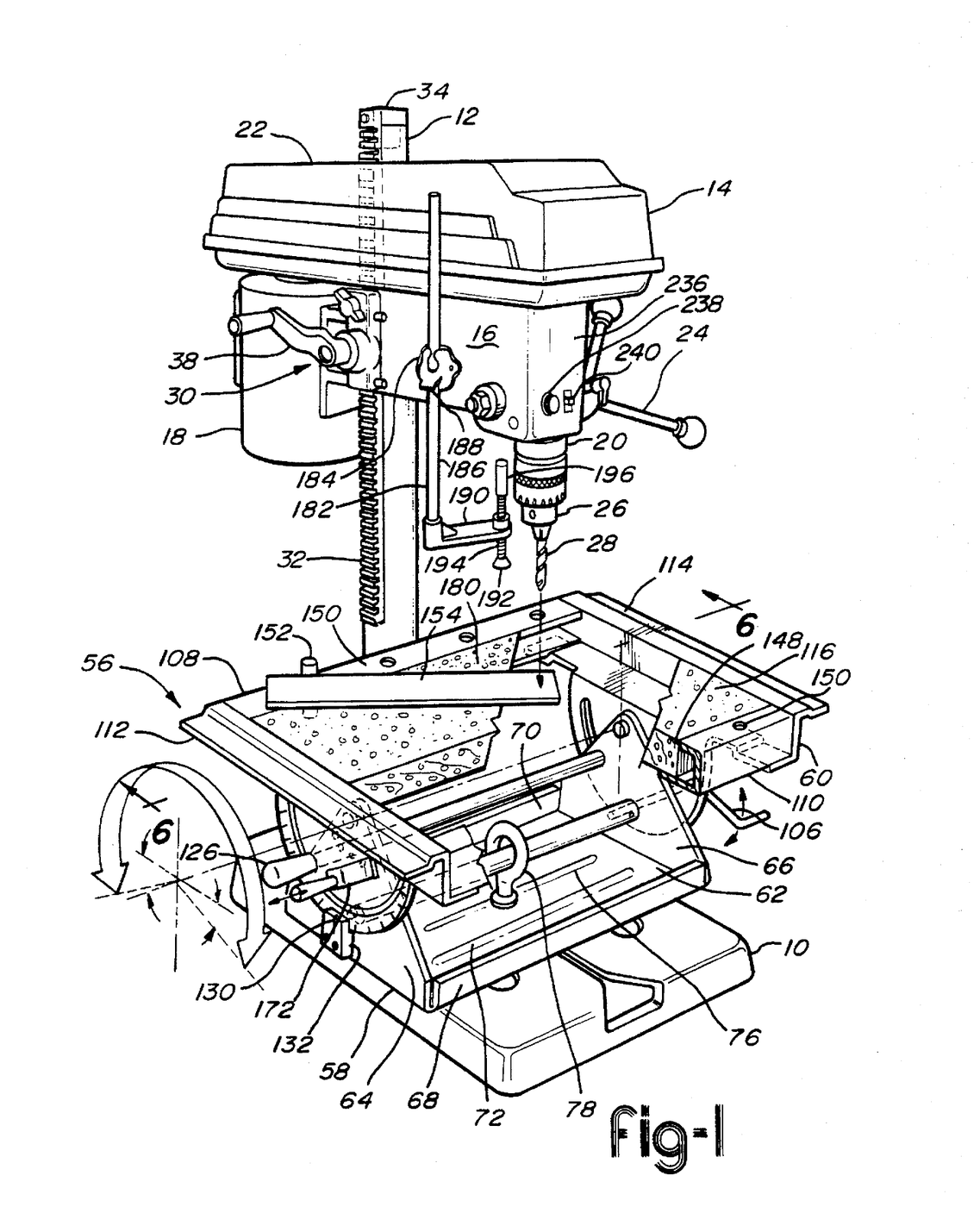
Most home drill presses kept the head fixed and moved the work relative to it. Kenneth M. Brazell and colleagues at Ryobi patented the reverse in 1997, US 5,634,748. A cast iron base sits on the work bench, a column rises from it, and the whole drill head, with its motor and quill, is raised and lowered along the column by a crank and a rack, or swung round it. A tilt table made of stamped and folded sheet steel locks to the base with one cam and eyebolt, slides two ways and turns on the base, and tilts to drill holes at an angle. Its replaceable ¾" particle board panel supports the stock underneath, preventing tear-out.
Avancé
Factory process

Consignes

1

Base and column

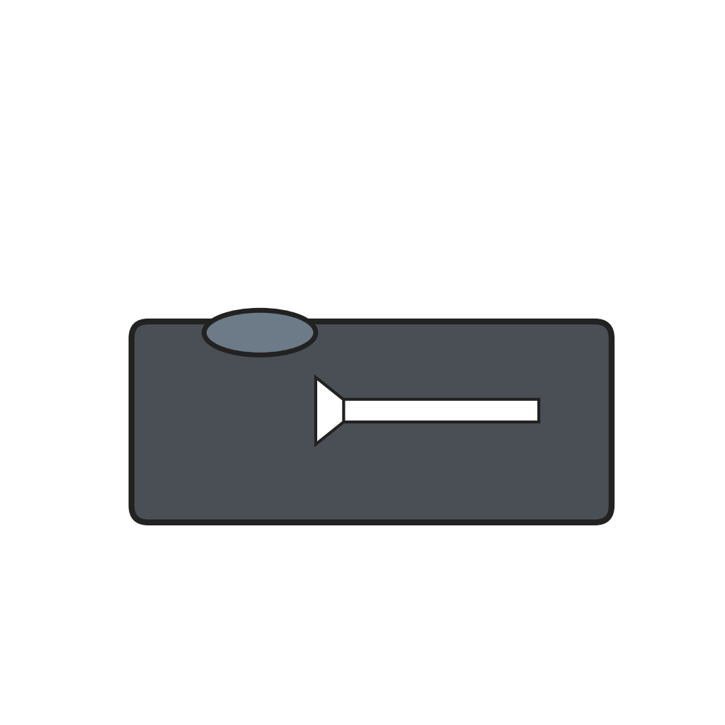
Cast the base with a collar near its rear end to take the column, a transverse slot with a funnel-shaped entrance at the front for the table's lock, and two keyhole slots whose round ends take standard ½ inch carriage bolts for clamping vices. Fix the column in the collar.

Matériaux pour cette étape :

Socle en fonte de perceuse à colonneSocle en fonte de perceuse à colonne1 pièce
Colonne de perceuseColonne de perceuse1 pièce

Outils nécessaires :
Poche de fonderiePoche de fonderie
Clé à moletteClé à molette
2

Rack on a turning cap

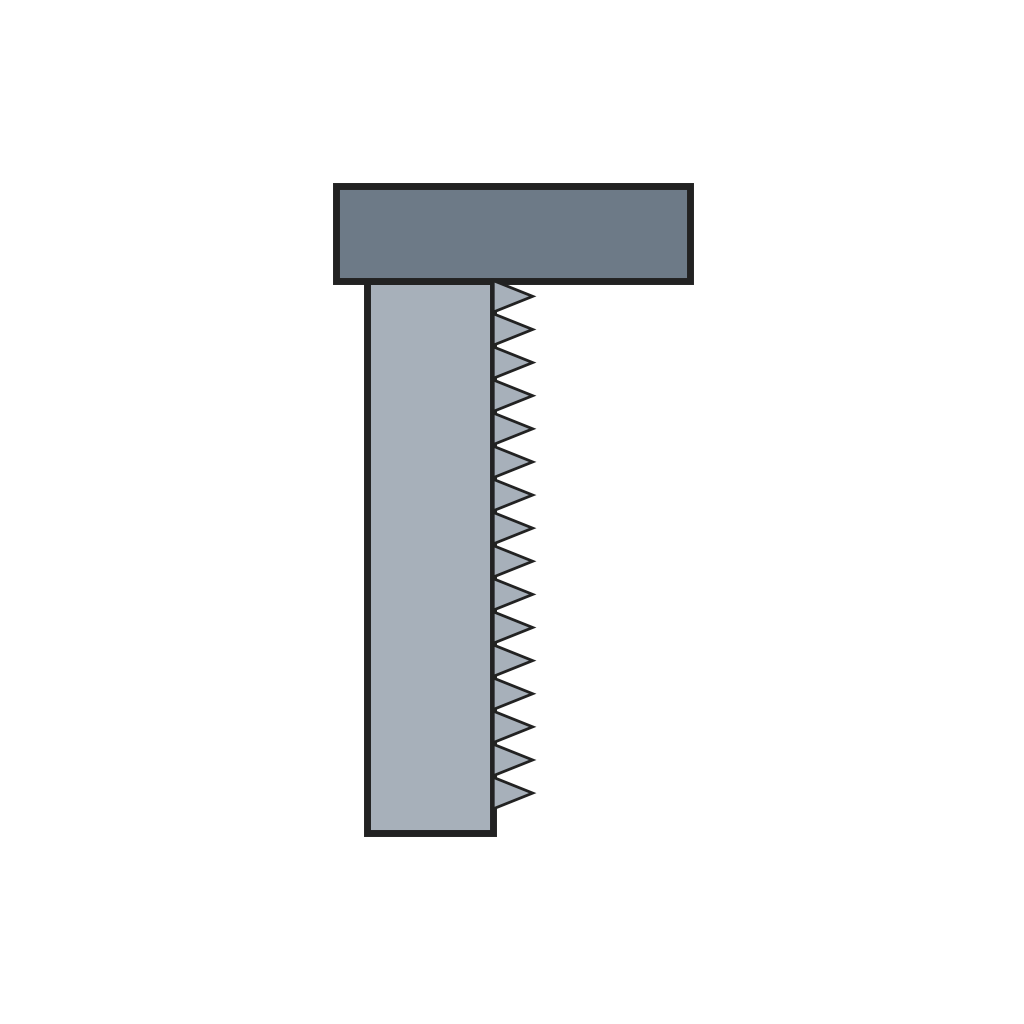
Screw the rack to a cap that fits over the top of the column. Two opposite pins in the column ride in an annular slot in the cap, so the cap turns but cannot lift off. The rack runs down most of the column's length.

Matériaux pour cette étape :

Crémaillère de colonne à chapeau tournantCrémaillère de colonne à chapeau tournant1 pièce

Outils nécessaires :
Jeu de tournevisJeu de tournevis
3

Head frame

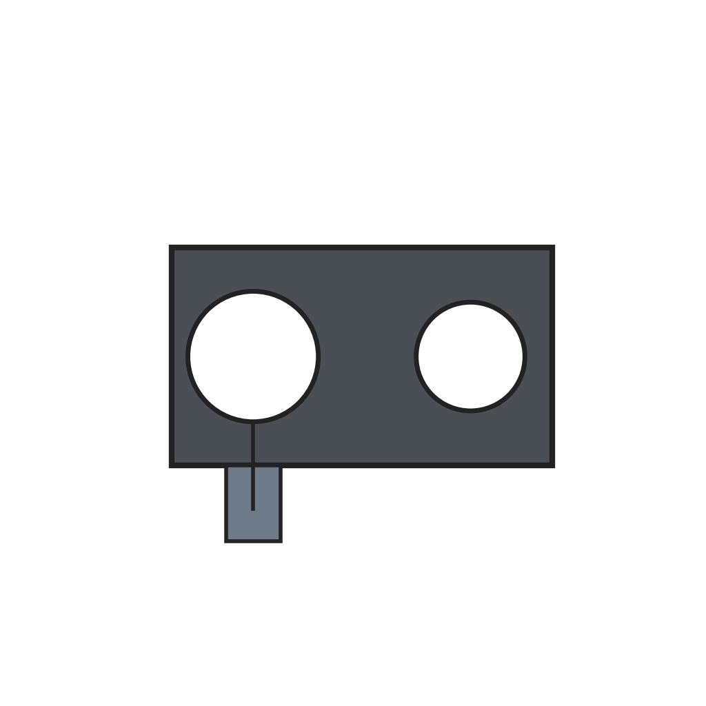
Make the head frame with a split C-section round the column, two clamping flanges and a slot through which the rack passes. A crank on the frame turns a pinion in the rack to raise and lower the head; a knobbed locking member through the flanges clamps the frame to the column. A spring-loaded indexing pin through a bracket on the rack drops into a bore in the column to lock the head over the centre of the base.

Matériaux pour cette étape :

Bâti de tête à collier de colonne fenduBâti de tête à collier de colonne fendu1 pièce
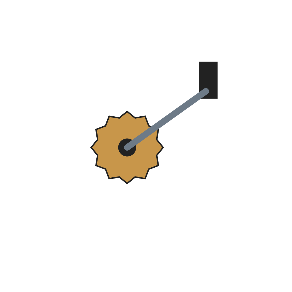
Manivelle et pignon de levage de têteManivelle et pignon de levage de tête1 pièce
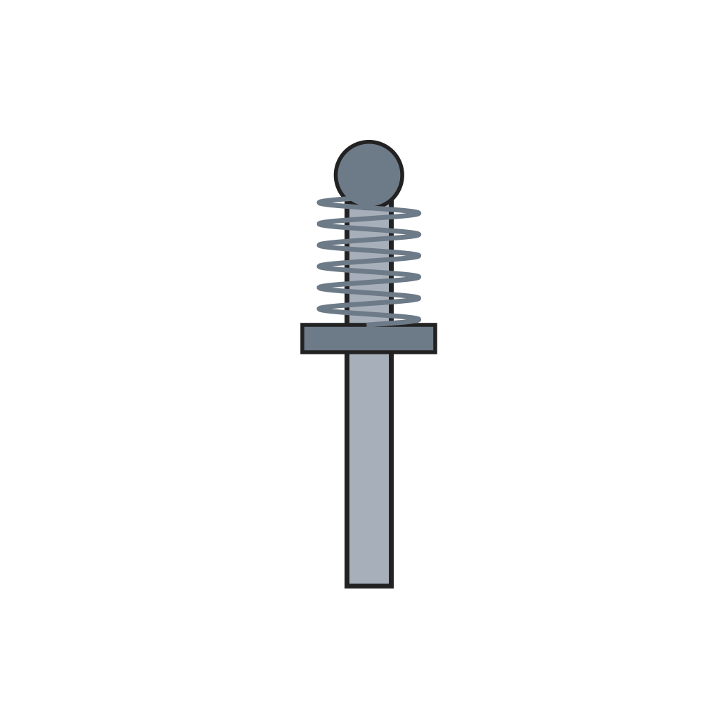
Doigt d'indexage à ressortDoigt d'indexage à ressort1 pièce

Outils nécessaires :

Jeu de tournevisJeu de tournevis
Pince universellePince universelle
4

Motor and belt

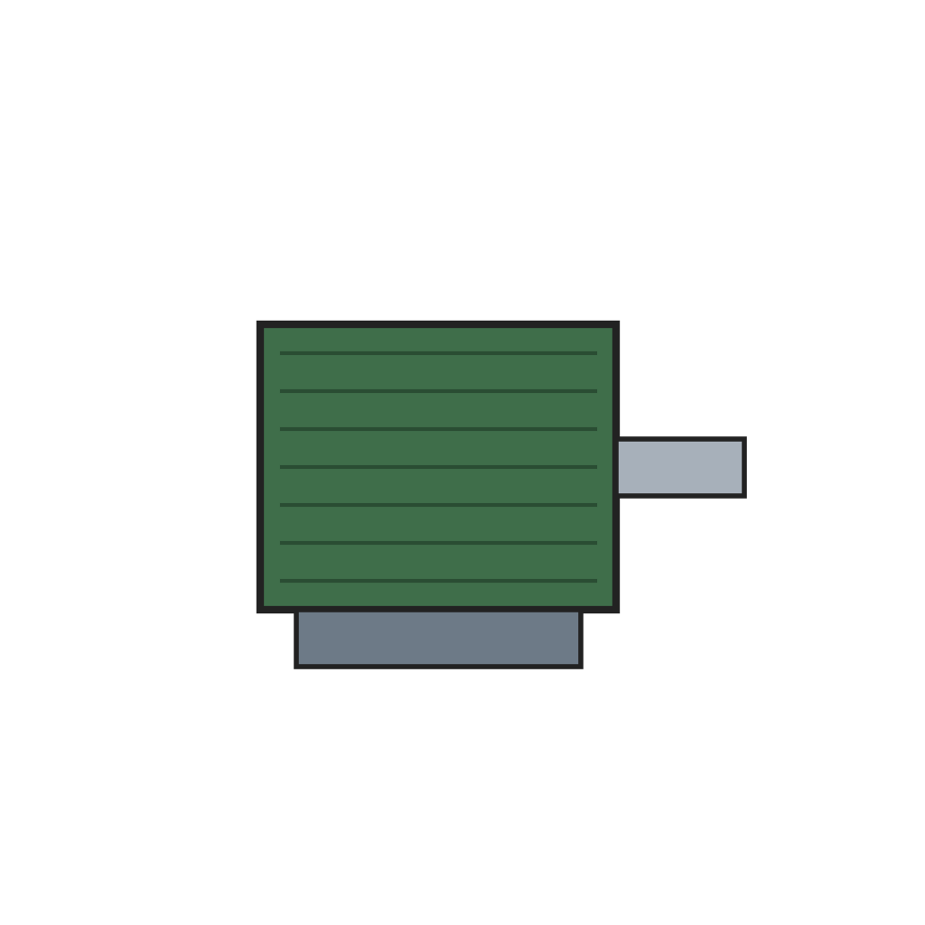
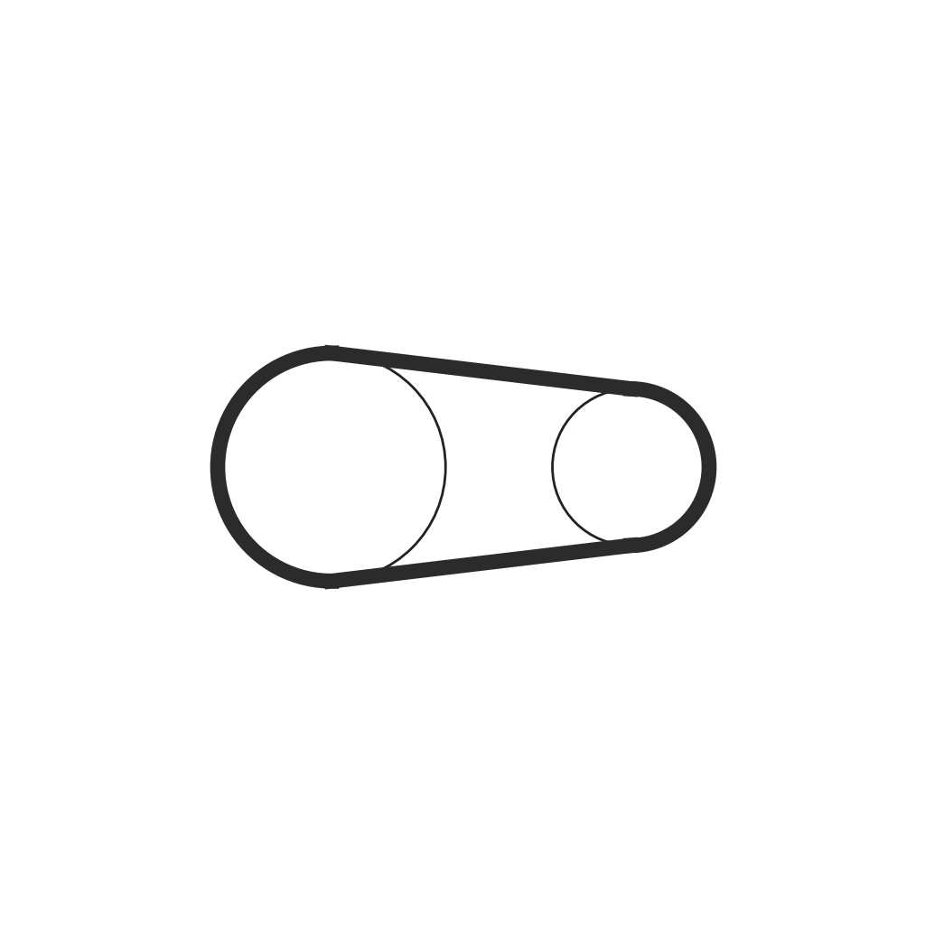
Mount the motor on a bracket that slides on a clamping rod and a parallel follower rod in a boss on the frame, on the opposite side of the column from the quill. A belt connects the motor to the quill; loosen the lock knob and slide the motor to tension the belt. A cover encloses the drive and its speed-change mechanism, with a clearance opening for the column. The on/off switch, speed control knob and light switch sit on the face of the frame.

Matériaux pour cette étape :

Moteur électriqueMoteur électrique1 pièce
Support de moteur coulissantSupport de moteur coulissant1 pièce
Courroie de transmissionCourroie de transmission1 pièce

Outils nécessaires :

Clé à moletteClé à molette
Jeu de tournevisJeu de tournevis
5

Quill and chuck

Fit the quill in the frame with a hand wheel that moves it up and down, and fit the chuck on its end to take the shanks of drill bits and other tools.

Matériaux pour cette étape :

Fourreau de perceuse à volant d'avanceFourreau de perceuse à volant d'avance1 pièce
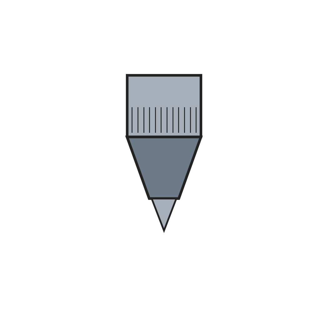
Mandrin de perçageMandrin de perçage1 pièce

Outils nécessaires :

Clé à moletteClé à molette
6

Tilt table

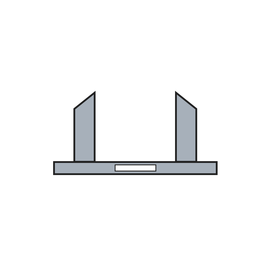
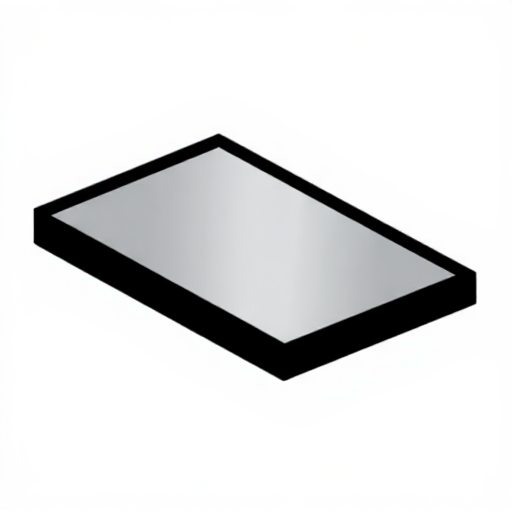
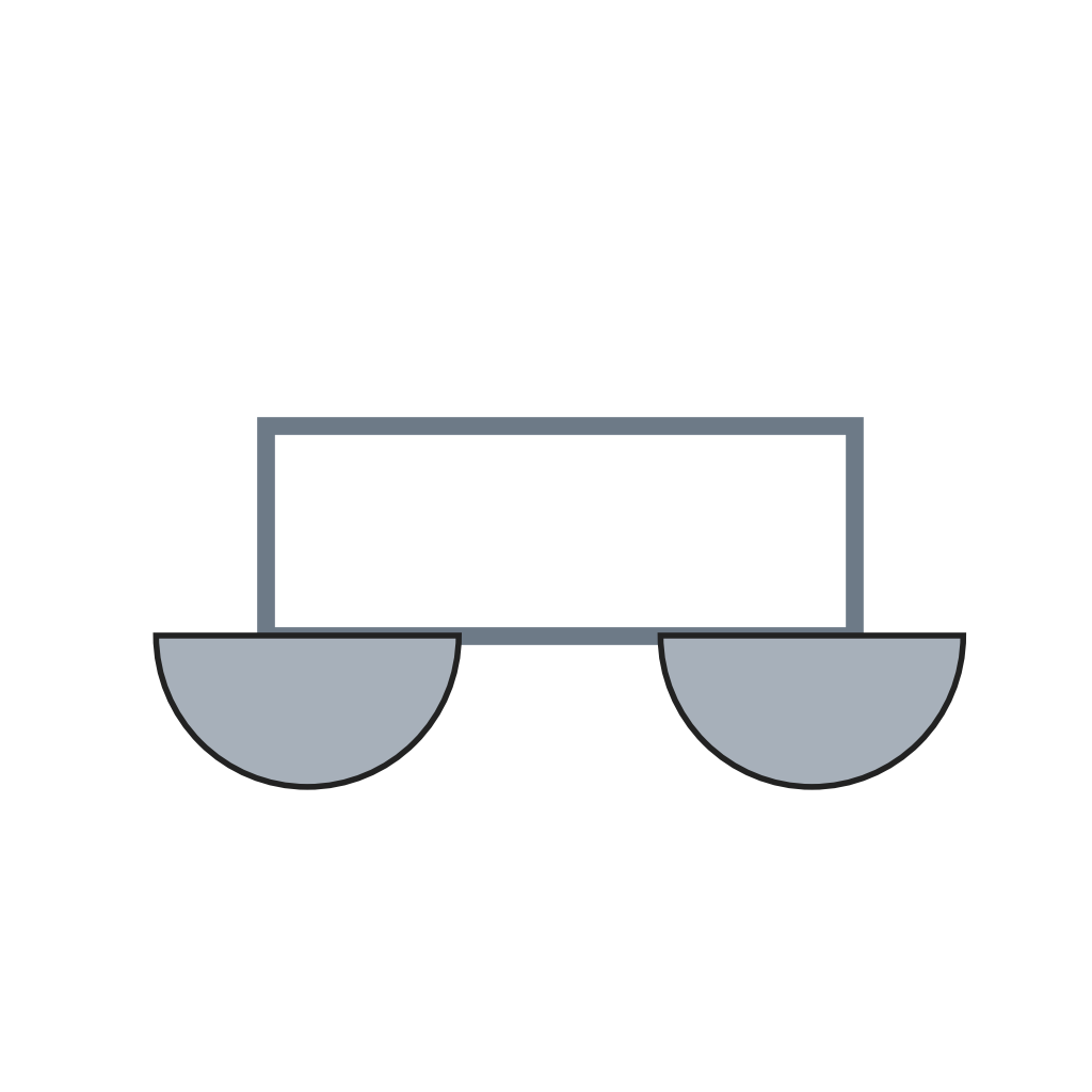
Stamp and fold the supporting base from 3.2 mm steel plate, with a flat base, two upright trunnions, side walls, stiffener ribs and a longitudinal slot. Pivot the table frame between the trunnions on its two sector disks, and lay the particle board panel in it. Pass an eyebolt through the slot and the base's transverse slot, with a nylon nut underneath. An eccentric camshaft between the trunnions runs through the eye; turning its crank lifts the eyebolt and clamps the table to the base, and turning it back frees the table to slide or turn.

Matériaux pour cette étape :

Socle de table inclinableSocle de table inclinable1 pièce
Plaque d'acier douxPlaque d'acier doux1 pièce
Cadre pivotant de table inclinableCadre pivotant de table inclinable1 pièce
Panneau de table en aggloméréPanneau de table en aggloméré1 pièce
Piton à œilPiton à œil1 pièce
Écrou en nylonÉcrou en nylon1 pièce
Arbre à came excentrique de blocageArbre à came excentrique de blocage1 pièce

Outils nécessaires :
Presse d'emboutissagePresse d'emboutissage
Clé à moletteClé à molette

Matériaux

18

Outils requis

5

Blueprints liés

Ces blueprints partagent des connaissances — techniques, matériaux ou principes
CC0 Domaine public

Ce blueprint est publié sous CC0. Vous êtes libre de copier, modifier, distribuer et utiliser ce travail pour tout usage, sans demander la permission.

Soutenez le Maker en achetant des produits via son Blueprint où il perçoit une Commission Maker définie par les Vendeurs, ou créez une nouvelle itération de ce Blueprint et incluez-le comme connexion dans votre propre Blueprint pour partager les revenus.

Commentaires

(0)

Se connecter pour participer à la discussion

Chargement des commentaires...