Collaboration
ART
BEAUTÉ ET BIEN-ÊTRE
ARTISANAT
CULTURE ET HISTOIRE
DIVERTISSEMENT
ENVIRONNEMENT
NOURRITURE ET BOISSONS
INGÉNIERIE INVERSE
SCIENCES
SPORTS
TECHNOLOGIE
TECHNOLOGIE PORTABLE
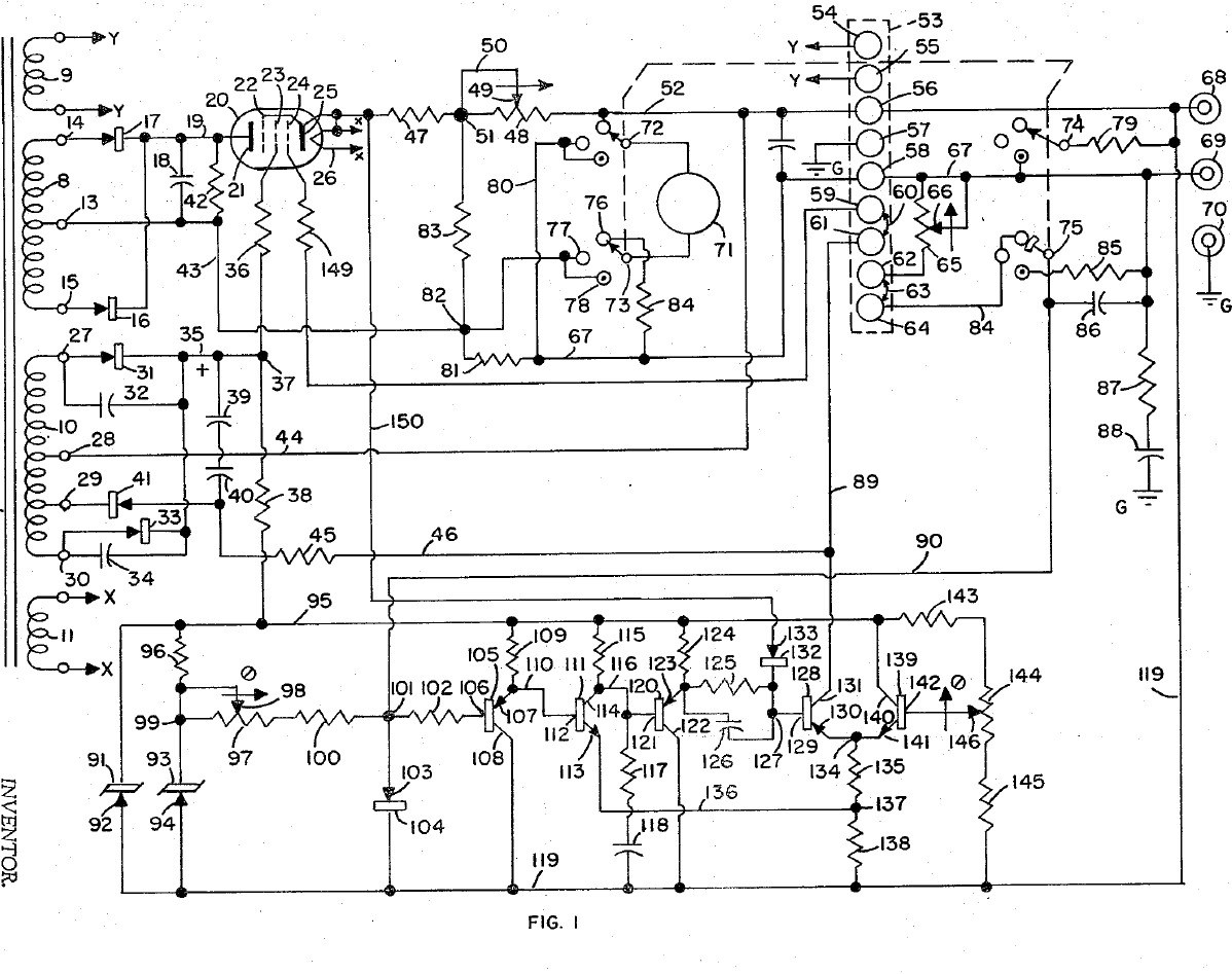


Bench Power Supply: Regulated, with Adjustable Current Limit and a Pentode Pass Tube (Gately, Forbro, US 3,243,690, 1966)
An adjustable bench supply that holds its output voltage steady and lets you set the most current it will deliver, so a circuit under test cannot be damaged. A pentode tube in series with the output is the regulator; a bridge with Zener references and a five-transistor amplifier keeps the output equal to the setting of one knob. A meter switch reads volts, amps, and the current limit, which can be set without disturbing the voltage.
Result: a regulated DC bench supply with adjustable current limiting.
Source: J. R. Gately (Forbro Design), US 3,243,690 (1966). Unknown: all component values and the output rating. Picture: the patent drawing.
Avancé
Unknown
Consignes
1
1
Wire the mains side
Wire the mains side
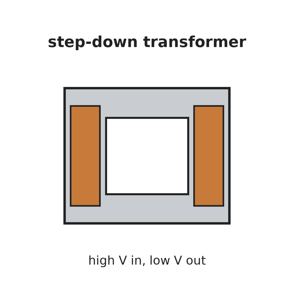
In a case, wire the power cord through a switch and a fuse to the primary of a transformer with four secondaries, and put a neon lamp across the primary to show the supply is on. One secondary (6.3 V) goes to two terminals for outside use, one heats the pentode, one is the main supply and one the bias supply. Ours: the case. Not given: the other winding voltages.
Matériaux pour cette étape :
 Boîtier en aluminium1 case
 Cordon souple avec fiche1 pièce
 Interrupteur à levier1 pièce
 Fusible1 pièce
 Transformateur abaisseur1 four secondaries
 Lampe témoin au néon1 pièce
 Borne de sortie2 6.3 V terminals
Outils nécessaires :
 Chignole à main
 Jeu de tournevis
2
2
Build the rectifiers
Build the rectifiers
Rectify the centre-tapped main winding with two rectifiers and smooth it with a capacitor. From the bias winding make two more supplies: one through two rectifiers with by-pass capacitors to a smoothing capacitor, for the pentode's screen and the reference circuit; the other through one rectifier and a capacitor, for the pentode's grid bias. Not given: the values.
Matériaux pour cette étape :
 Diode5 rectifiers
 Condensateur électrolytique3 smoothing
 Kit de condensateurs1 by-pass
 Fil de soudure1 as needed
Outils nécessaires :
 Fer à souder
3
3
Fit the pass tube and reference
Fit the pass tube and reference
Put the pentode in series with the positive output: plate to the main supply, cathode through two current-sensing resistors (one fixed, one adjustable) to the + output terminal; suppressor tied to the cathode, screen fed through a resistor. Build the reference: a Zener fed through a resistor feeds a second Zener at constant current, giving a fixed voltage. Against it set two resistors and the voltage-control variable resistor: the output voltage is proportional to that resistor's setting. Not given: the tube type and values.
Matériaux pour cette étape :
 Tube pentode1 series pass tube
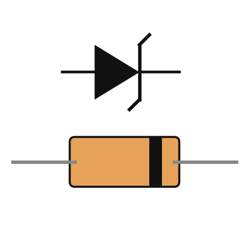 Diode Zener2 pièces
 Résistance1 jeu
 Rhéostat2 voltage control, current-limit rangeBorne de sortie2 output + and -Fil de soudure1 as needed
Outils nécessaires :
Fer à souder4
4
Build the error amplifier and current limit
Build the error amplifier and current limit
Build a five-transistor amplifier that drives the pentode's grid to keep the bridge balanced: a PNP emitter follower, an NPN stage, a PNP emitter follower with a resistor-capacitor roll-off against oscillation, a PNP driver whose base resistor has a capacitor across it for quick response, and an NPN clamp whose base is set by a potentiometer. Feed the voltage across the current-sensing resistors to the driver's base through a diode: above the limit it takes over and turns the pentode down. Choose the fixed sensing resistor to limit at about 125 % of rated current, trim with the potentiometer, and use the adjustable one to set lower limits. Not given: the transistor types and values.
Matériaux pour cette étape :
 Transistor PNP3 pièces
 Transistor NPN2 piècesDiode1 pièce
 Potentiomètre1 pièceKit de condensateurs1 roll-off, speed-upRésistance1 jeuFil de soudure1 as needed
Outils nécessaires :
Fer à souder5
5
Fit the meter and use it
Fit the meter and use it
Fit a meter with a four-pole, three-position switch. Position 1 reads output volts through a multiplier resistor; position 2 reads current across a shunt in the negative line; position 3 (spring-return) puts a load resistor across the output and swaps a fixed resistor for the voltage control, so you can turn the limit control until the current limits at the value you want, without touching the voltage setting. Release the switch and use the supply.
Matériaux pour cette étape :
 Appareil de tableau à cadre mobile1 pièce
 Commutateur rotatif1 4-pole, 3-positionRésistance1 multiplier, shunt, load resistors
 Matériau inconnu1 terminal strip
Outils nécessaires :
Fer à souderJeu de tournevisMatériaux
21- 1 caseEspace réservé
- 1 pièceEspace réservé
- Espace réservé
- 1 pièceEspace réservé
- 1 four secondariesEspace réservé
- 1 pièceEspace réservé
- Espace réservé
- 1 pièceEspace réservé
- 3 smoothingEspace réservé
- 1 roll-off, speed-upEspace réservé
- 3 as neededEspace réservé
- 1 series pass tubeEspace réservé
- 2 piècesEspace réservé
- 1 multiplier, shunt, load resistorsEspace réservé
- 2 voltage control, current-limit rangeEspace réservé
- 3 piècesEspace réservé
- 2 piècesEspace réservé
- Espace réservé
- Espace réservé
- 1 4-pole, 3-positionEspace réservé
- 1 terminal stripEspace réservé
Ce plan fabrique

CC0 Domaine public
Ce blueprint est publié sous CC0. Vous êtes libre de copier, modifier, distribuer et utiliser ce travail pour tout usage, sans demander la permission.
Soutenez le Maker en achetant des produits via son Blueprint où il perçoit une Commission Maker définie par les Vendeurs, ou créez une nouvelle itération de ce Blueprint et incluez-le comme connexion dans votre propre Blueprint pour partager les revenus.