ART
BEAUTÉ ET BIEN-ÊTRE
ARTISANAT
CULTURE ET HISTOIRE
DIVERTISSEMENT
ENVIRONNEMENT
NOURRITURE ET BOISSONS
AVENIR VERT
INGÉNIERIE INVERSE
SCIENCES
SPORTS
TECHNOLOGIE
TECHNOLOGIE PORTABLE
Traduit
BLUEPRINT NFT

Clignotement LED — Votre Premier Projet Arduino
Le projet électronique classique pour débuter ! Construisez un circuit LED clignotant avec un Arduino, une breadboard, une résistance et une seule LED. Parfait pour les débutants absolus — aucune soudure requise.
Consignes
1
1
Rassemblez vos composants
Rassemblez vos composants
Rassemblez tous les composants énumérés ci-dessous. Aucune soudure nécessaire — tout se branche sur la planche d'essai.
Matériaux pour cette étape :
 SparkFun Inventor's Kit - V3.21 kit
Arduino Uno R31 pièce
5mm LED (any color)1 pièce
 220 ohm Resistor (1/4W)1 pièce
Breadboard1 pièce
Jumper Wires (Male-to-Male)2 pièces
USB-B Cable1 pièce
Outils nécessaires :
Computer with Arduino IDE
2
2
Schéma du Circuit
Schéma du Circuit
Le signal circule de la broche Arduino 13 → résistance 220Ω (R1) → LED (D1) → GND. La résistance limite le courant pour protéger le LED.
Matériaux pour cette étape :
Arduino Uno R31 pièce
5mm LED (any color)1 pièce
220 ohm Resistor (1/4W)1 pièce3
3
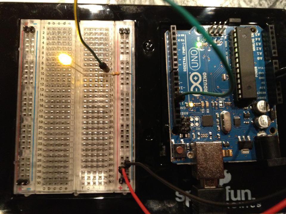
Connectez-le
Connectez-le
- Insérez le LED dans la breadboard — patte longue (anode +) dans une rangée, patte courte (cathode −) dans la suivante.
- Insérez une patte de la résistance 220Ω dans la même rangée que la cathode LED. L'autre patte dans une rangée séparée.
- Fil de liaison de la rangée anode LED → Arduino Pin 13.
- Fil de liaison de la rangée libre de la résistance → Arduino GND.
Matériaux pour cette étape :
5mm LED (any color)1 pièce
220 ohm Resistor (1/4W)1 pièceBreadboard1 pièce
Jumper Wires (Male-to-Male)2 pièces
4
4
Téléverser le code Blink
Téléverser le code Blink
Connectez Arduino via USB. Ouvrez Arduino IDE, sélectionnez Tools → Board → Arduino Uno, collez le code et cliquez sur Upload.
blink.inoarduino
Matériaux pour cette étape :
Arduino Uno R31 pièce
USB-B Cable1 pièce
Outils nécessaires :
Computer with Arduino IDE
5
5
PCB Disposition (Référence)
PCB Disposition (Référence)
Ceci montre le circuit en tant que disposition PCB. Non nécessaire pour ce projet — la breadboard fonctionne parfaitement — mais montre comment le même circuit ressemblerait s'il était fabriqué en tant que vrai circuit imprimé.
6
6
Test et Expérience
Test et Expérience
LED clignote ? Félicitations ! Vous venez de programmer du matériel.
Dépannage :
Expériences suivantes :
Dépannage :
- LED ne s'allume pas ? Retournez le LED — la longue patte vers la broche 13.
- LED reste allumé ? Vérifiez que le code a été téléchargé avec succès.
- Rien ne se passe ? Vérifiez que le câblage correspond au schéma de l'étape 2.
Expériences suivantes :
- Modifiez les valeurs de
delay()pour contrôler la vitesse de clignotement - Ajoutez un deuxième LED sur la broche 12
- Remplacez par un RGB LED (voir le circuit SIK 3)
Matériaux
7- €90.00
- Espace réservé
Total estimé
€90.00Related blueprints
Other builds that share materials, tools, or techniques with this one.

Using a Shift Register — SIK Circuit 14electronics/active
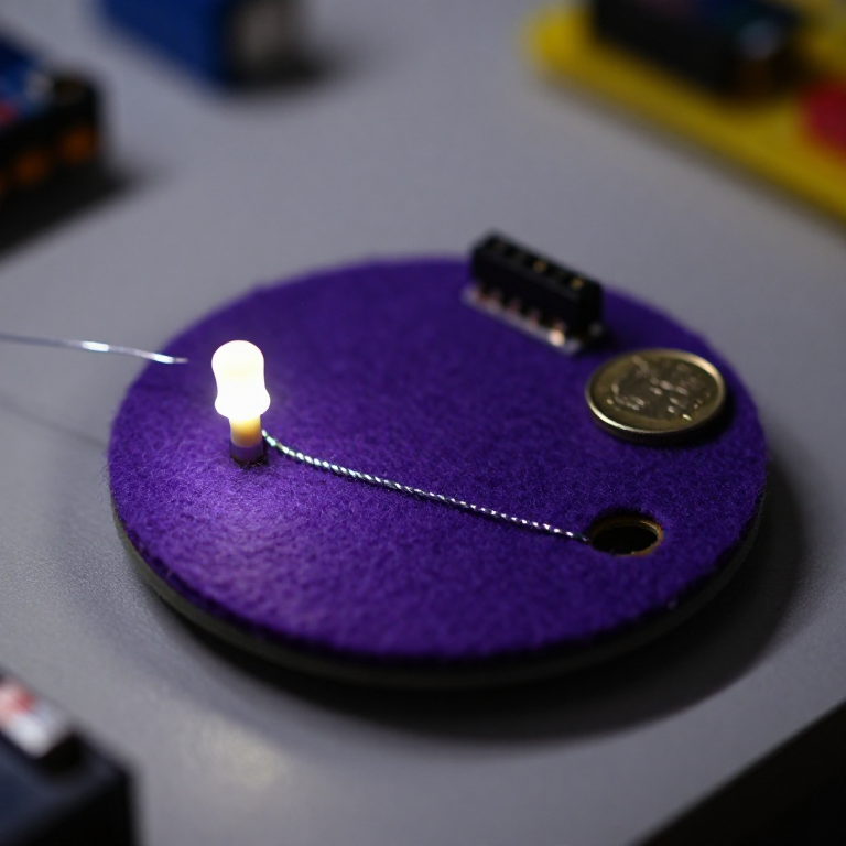
Blinking an LED with LilyPad Arduinoelectronics

Making Charcoal — The First Chemical Processmaterials
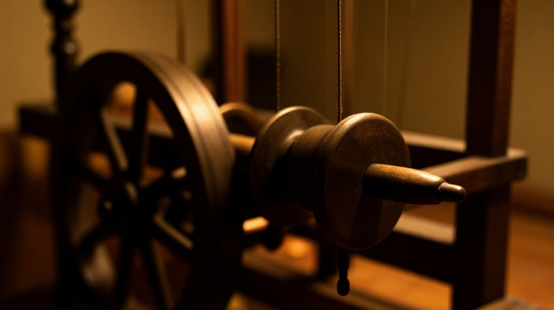
The Spinning Jenny — Multi-Spindle Yarn Productiontextiles

Starting Seeds Indoors — Raising Seedlings for a Head Start

Driving a Motor — SIK Circuit 12electronics/electromech
CC0 Domaine public
Ce blueprint est publié sous CC0. Vous êtes libre de copier, modifier, distribuer et utiliser ce travail pour tout usage, sans demander la permission.
Soutenez le Maker en achetant des produits via son Blueprint où il perçoit une Commission Maker définie par les Vendeurs, ou créez une nouvelle itération de ce Blueprint et incluez-le comme connexion dans votre propre Blueprint pour partager les revenus.