ART
BEAUTÉ ET BIEN-ÊTRE
ARTISANAT
CULTURE ET HISTOIRE
DIVERTISSEMENT
ENVIRONNEMENT
NOURRITURE ET BOISSONS
INGÉNIERIE INVERSE
SCIENCES
SPORTS
TECHNOLOGIE
TECHNOLOGIE PORTABLE

Youblob (drawn from the sketch's pin map) · CC0

Bring-Up: The First Hour with Your Own Chip, Tested by an ESP32
Bring-up is what engineers call the first power-on of new silicon, and the order of it matters more than any single test. Look before you power, power before you clock, and limit the current before you do anything, because a short that a current limit would have caught in a second can destroy the only chips you have.
This rung is the bring-up plan for the PWM dimmer of the earlier rungs, on the breakout board from rung 2. An ESP32 does the work of a lab: it makes the chip's clock, holds its reset, sets the duty on eight pads and times the PWM that comes back, then prints PASS or FAIL for each duty. A notebook turns a failure into the name of the pad whose wire is wrong.
Honestly stated: there is no chip yet. The sketch was compiled for this blueprint and the expected numbers come from the simulations of the earlier rungs; the first real run is yours.
Avancé
An afternoon, once the chip arrives
Consignes
1
1
The numbers to expect, and how to read a failure
The numbers to expect, and how to read a failure
Chargement du notebook Jupyter…
2
2
The chip you are bringing up
The chip you are bringing up
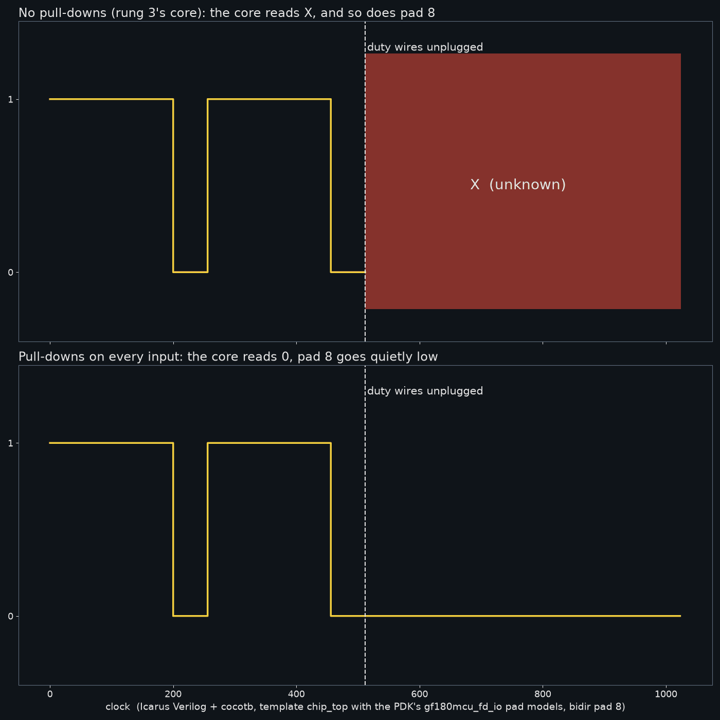
The embedded blueprint puts pull-downs on every input, so an unplugged chip sits disabled. That is the core this plan tests.
3
3
Before any power
Before any power
With nothing connected, look at the chip-on-board seated on the breakout under the loupe: seated square, no solder bridge, nothing loose. Then measure the resistance between a VDD IO pad and a GND IO pad of the breakout with the multimeter, in both polarities, and write both numbers down. A reading near zero is a short: stop there. The run-1 pad table names which breakout pads are VDD IO and GND IO; use your run's table, because wafer.space says pinouts change between runs.
Check the same way that no data pad is shorted to its neighbour or to ground.
Matériaux pour cette étape :
 Puce ASIC sur mesure1 pièce
 Circuit imprimé1 pièce
Outils nécessaires :
 Multimètre
4
4
Power, with the current limit low
Power, with the current limit low
Set the bench supply to your chip's supply voltage before connecting it. That voltage depends on the libraries your chip was built with: the template's default libraries are 5 V ones, and it can also build with 3.3 V libraries. Take the exact value from your run's documentation; the run-1 pad table names the power pads but not their voltage.
Set the current limit to the lowest setting that lets the supply regulate, connect VDD IO and GND IO, and switch on with the ESP32 still disconnected. With no clock and every input pulled down, the chip should sit still. Write down the current. If the supply goes straight into current limiting, switch off: something is shorted.
Record the current twice more later, in reset with the clock running and while it plays a pattern. Those three numbers are your chip's own signature; a board that later draws much more than it did today has a fault.
Outils nécessaires :
 Alimentation de laboratoireMultimètre
5
5
Wire the ESP32
Wire the ESP32
Twelve wires, as in the picture and in the sketch's header: GPIO 27 to the clock pad, 26 to rst_n, 32 to input 0 (enable), 13, 14, 18, 19, 21, 22, 23 and 25 to bidirectional pads 0 to 7, and bidirectional pad 8 back to GPIO 34, plus a common ground. GPIO 34 is an input-only pin on the ESP32, so it can never fight the chip's output.
The ESP32 is a 3.3 V part and its inputs are not 5 V tolerant. If your chip's I/O is not 3.3 V, put level converters in all twelve lines: three four-channel boards. The common kind has pull-up resistors on both sides, which may override the chip's weak pull-downs until the ESP32 drives its pins; the sketch holds reset and enable low as soon as it starts, before the clock runs.
Matériaux pour cette étape :
 Adaptateur de niveaux logiques3 pièces
 Jeu de fils de liaison1 pièce
Outils nécessaires :
 Breadboard - Classic
6
6
The test sketch
The test sketch
bringup.ino. It starts the chip's clock with the ESP32's LED PWM peripheral at 100 kHz, with 1-bit resolution for a plain square wave; holds reset low for 1,000 chip clocks; checks that the output stays low while enable is off; then sets seven duty values and measures the high time with pulseIn, averaged over eight periods, against 10 microseconds per step, within 3 microseconds. It compiles for the ESP32 with the Arduino ESP32 core 3.3.12; it has not been run, because the chip does not exist yet.
bringup.inocpp
Outils nécessaires :
 Carte de développement ESP32
 Ordinateur de bureau
7
7
What a good chip prints
What a good chip prints
Open the serial monitor at 115200 baud. A chip that works prints, per line, the duty, the expected and measured high time in microseconds, and the result:
# chip clock 100000 Hz, PWM period 2560 us
duty,expected_us,measured_us,result
disabled,0,0,PASS
0,0.0,0.0,PASS
1,10.0,10.0,PASS
...
254,2540.0,2540.0,PASS
# 0 failure(s)
Then look at pad 8 with the oscilloscope as well: one period should be 2,560 microseconds at this clock, with clean edges. The sketch measures time; the scope shows shape, and a slow or ringing edge through a level converter is visible only there.
Outils nécessaires :
 Oscilloscope numérique
8
8
A chip that does not come up
A chip that does not come up
Bring-up troubleshooting.
Flow
Loading...
9
9
Sources and honest limits
Sources and honest limits
**Sources**, read 29 September 2026: wafer-space/chip-on-board-wire-bonded-pcbs, run-1/README.md (the pad table naming VDD IO and GND IO pads, and the note that pinouts change between runs); wafer-space/gf180mcu-project-template, README.md and Makefile (the 5 V default and 3.3 V library options); the earlier rungs' simulations for the expected high times.
**Honest limits.** No chip exists yet: this plan and its sketch have not been run on silicon. The supply voltage and current are not stated here because the run documentation available at the time of writing does not state them. The level converter's effect on the pull-downs depends on the board you use.
Matériaux
4- 1 pièceEspace réservé
- 1 pièceEspace réservé
- 3 piècesEspace réservé
- 1 pièceEspace réservé
Outils requis
6- Espace réservé
- Espace réservé
- Breadboard - Classic10 % de commission€8.29
- Espace réservé
- Espace réservé
- Oscilloscope numérique10 % de commissionMagento Legacy Storeships internationallyEspace réservé
Blueprints liés
Ces blueprints partagent des connaissances — techniques, matériaux ou principes
Through the Pads: What Your Chip's Pins Do When Nothing Is Connected
par Ed
Électronique
1
0
0
0
0
0

The Chip-on-Board Breakout: From a 0.4 mm Mezzanine to Pins You Can Reach
par Ed
Électronique
3
0
0
0
0
0

Your Own chip_core: An 8-bit PWM Dimmer, Tested Before It Is Silicon
par Ed
Électronique
1
0
0
0
0
0

Your First Chip on a Shared Wafer: What You Need to Start at Home
par Ed
Électronique
4
0
0
0
0
0
CC0 Domaine public
Ce blueprint est publié sous CC0. Vous êtes libre de copier, modifier, distribuer et utiliser ce travail pour tout usage, sans demander la permission.
Soutenez le Maker en achetant des produits via son Blueprint où il perçoit une Commission Maker définie par les Vendeurs, ou créez une nouvelle itération de ce Blueprint et incluez-le comme connexion dans votre propre Blueprint pour partager les revenus.