
ART
BEAUTÉ ET BIEN-ÊTRE
ARTISANAT
CULTURE ET HISTOIRE
DIVERTISSEMENT
ENVIRONNEMENT
NOURRITURE ET BOISSONS
INGÉNIERIE INVERSE
SCIENCES
SPORTS
TECHNOLOGIE
TECHNOLOGIE PORTABLE
Glass Saw: Rigid Diamond Wire Ring Driven by Its Rim
Martin

Créé par

Martin

23. octobre 2026NO
15
0
0
0
0

Glass Saw: Rigid Diamond Wire Ring Driven by Its Rim

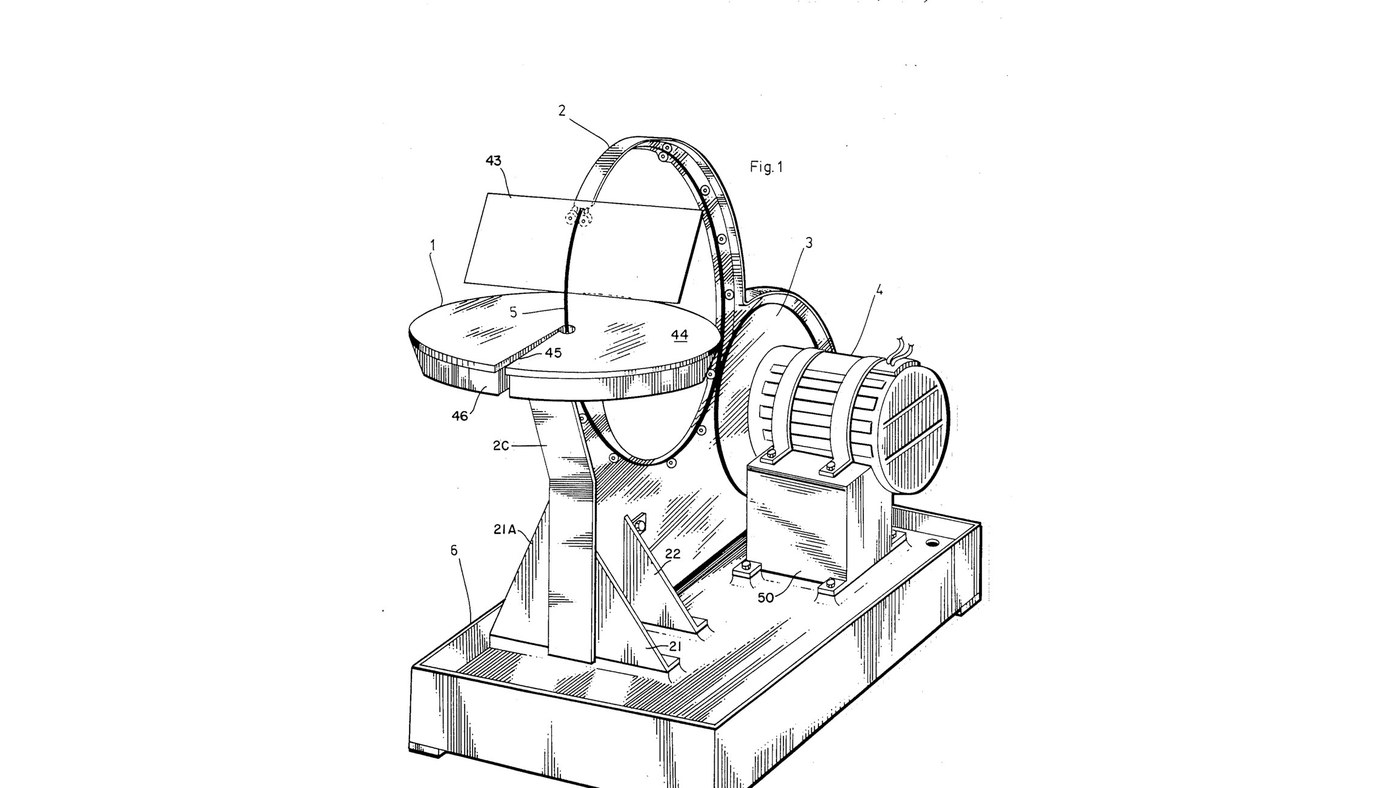
Jesse Cogswell's ring saw (US 4,576,139, 1986) for glass, ceramics and stone. The blade is a rigid circle of wire coated with bonded diamond, standing upright through a cutting table. A rubber-tyred wheel on the motor drives it by friction round its own rim at 3000 ft/min or more, and twelve guide wheels on slots round an aluminium back-plate hold it true. Because it cuts with any part of its rim, the work can be turned freely for curves and inside shapes; a sponge in a water tray wets the wire. The patent sizes the ring from the thickest work to be cut (8 in ring for 3/16 in); the notebook does the sums. The picture: the patent's Fig. 1.
Avancé
3 days

Consignes

1

Cut and brace the back-plate

Cut the back-plate (2A) from aluminium plate, its upper part curved as an arc to shield the saw, stiffened by an angle (2B) along the top and a flat splatter strip (2C) at the front. Bolt on two front struts (21, 21A) and two side struts (22) and bolt them to the base. Ours: drill press.

Matériaux pour cette étape :

Plaque d'aluminiumPlaque d'aluminium1 pièce
Cornière en aluminiumCornière en aluminium1 pièce
Boulon à tête hexagonale - classe 8.8Boulon à tête hexagonale - classe 8.81 pièce

Outils nécessaires :
Perceuse à colonnePerceuse à colonne
Clé à moletteClé à molette
2

Cut the wheel-slider apertures

Cut slots (32) through the back-plate's arc at 0, 30, 60, 90, 120, 210, 240, 270, 300 and 330° round the ring's centre: two slots at 90° and 210° for the guide pairs, one at each of the others. The slots let each guide wheel slide to the ring.

Outils nécessaires :

Perceuse à colonnePerceuse à colonne
3

Assemble the guide wheels

For each of the twelve guide wheels, stretch two rubber O-rings (27) into the grooves of a bearing wheel (26) with sealed roller bearings, and mount it on a shoulder bolt (28) with a washer, lockwasher and nut.

Matériaux pour cette étape :

Galet de guidageGalet de guidage12 pièces
Joint toriqueJoint torique24 pièces
Vis à épaulementVis à épaulement12 pièces
Rondelle plateRondelle plate12 pièces
Spring WasherSpring Washer12 pièces
Écrou hexagonalÉcrou hexagonal12 pièces

Outils nécessaires :

Clé à moletteClé à molette
4

Turn the drive wheel

Turn an aluminium disk with a hub, a bored axle hole and a deep groove round its rim, and seat a large rubber O-ring (23) in the groove as its driving tyre. Ours: lathe.

Matériaux pour cette étape :

Plaque d'aluminiumPlaque d'aluminium1 pièce
Joint toriqueJoint torique1 pièce

Outils nécessaires :

Tour à métauxTour à métaux
5

Mount the motor and drive axle

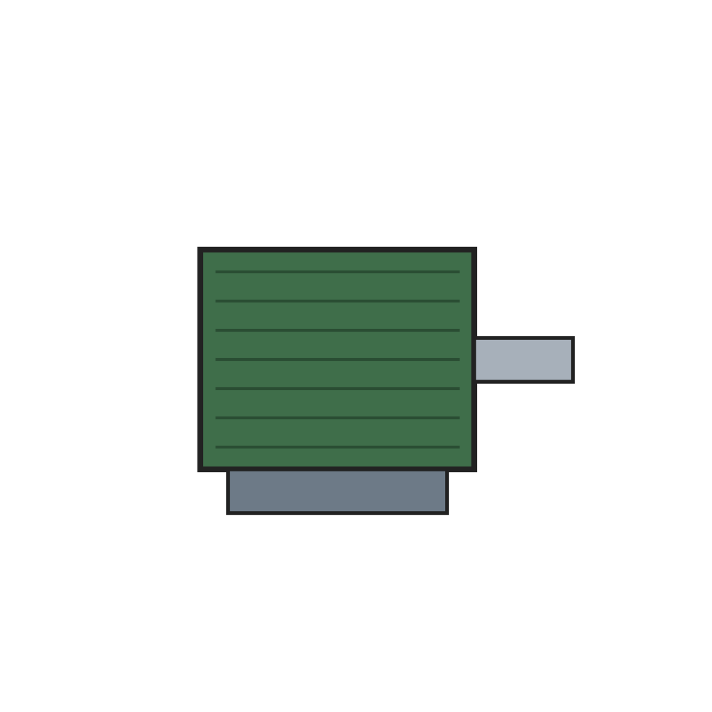
Strap the electric motor (51) onto its pillow block (50) with fastening bands (52) and bolt the block to the base. Fix the drive wheel on the motor's axle (24) and carry the axle's end in an axle pillow block (24A, 24B).

Matériaux pour cette étape :

Moteur électriqueMoteur électrique1 pièce
Collier de fixation de moteurCollier de fixation de moteur2 pièces
Palier supportPalier support2 pièces
Arbre en acierArbre en acier1 pièce
Boulon à tête hexagonale - classe 8.8Boulon à tête hexagonale - classe 8.81 pièce

Outils nécessaires :

Clé à moletteClé à molette
6

Fit the ring and its guides

Stand the ring saw on the drive wheel's tyre. Bolt the guide wheels through their slots: each pair with a tension spring between its two wheels, each single with a spring to the back-plate's lower rim, the one at 330° pressing the ring onto the drive wheel. Set them against the ring, then tighten the nuts. Fit two horizontal roller-guides (17) at 150°, sprung together, just before the cut.

Matériaux pour cette étape :

Lame de scie annulaire diamantéeLame de scie annulaire diamantée1 pièce
Ressort de tractionRessort de traction11 pièces
Galet de guidageGalet de guidage2 pièces

Outils nécessaires :

Clé à moletteClé à molette
7

Fit the table, tray and sponge

Bolt the water tray (46) on four bracket supports (19, 20) by its four studs; put a ring-shaped sponge (47) in it and the cutting table (44) over it, the ring passing through centre holes reached by slots offset half an inch from a radius. Set the table top below the ring's centre line by the thickest work you will cut. Add water to the tray.

Matériaux pour cette étape :

PlateauPlateau1 pièce
ÉpongeÉponge1 pièce
Plaque d'aluminiumPlaque d'aluminium1 pièce
EauEau1 batch

Outils nécessaires :

Clé à moletteClé à molette
8

Fit the face shield and drip pan

Bolt the shield arm (41) to the back-plate and pivot a clear acrylic face shield (43) in its holder (42) on a locking screw. The base is a catchment for the coolant with a drain hole in one corner.

Matériaux pour cette étape :

Plaque acryliquePlaque acrylique1 pièce
Plaque d'aluminiumPlaque d'aluminium1 pièce
Bac d'égouttageBac d'égouttage1 pièce

Outils nécessaires :

Clé à moletteClé à molette
9

Ring size and drive speed

Chargement du notebook Jupyter…

Matériaux

20

Outils requis

3

CC0 Domaine public

Ce blueprint est publié sous CC0. Vous êtes libre de copier, modifier, distribuer et utiliser ce travail pour tout usage, sans demander la permission.

Soutenez le Maker en achetant des produits via son Blueprint où il perçoit une Commission Maker définie par les Vendeurs, ou créez une nouvelle itération de ce Blueprint et incluez-le comme connexion dans votre propre Blueprint pour partager les revenus.

Commentaires

(0)

Se connecter pour participer à la discussion

Chargement des commentaires...