
ART
BEAUTÉ ET BIEN-ÊTRE
ARTISANAT
CULTURE ET HISTOIRE
DIVERTISSEMENT
ENVIRONNEMENT
NOURRITURE ET BOISSONS
INGÉNIERIE INVERSE
SCIENCES
SPORTS
TECHNOLOGIE
TECHNOLOGIE PORTABLE
Metal Band Saw: Horizontal Saw on a Welded Steel Frame
Martin

Créé par

Martin

23. octobre 2026NO
9
0
0
0
0

Metal Band Saw: Horizontal Saw on a Welded Steel Frame

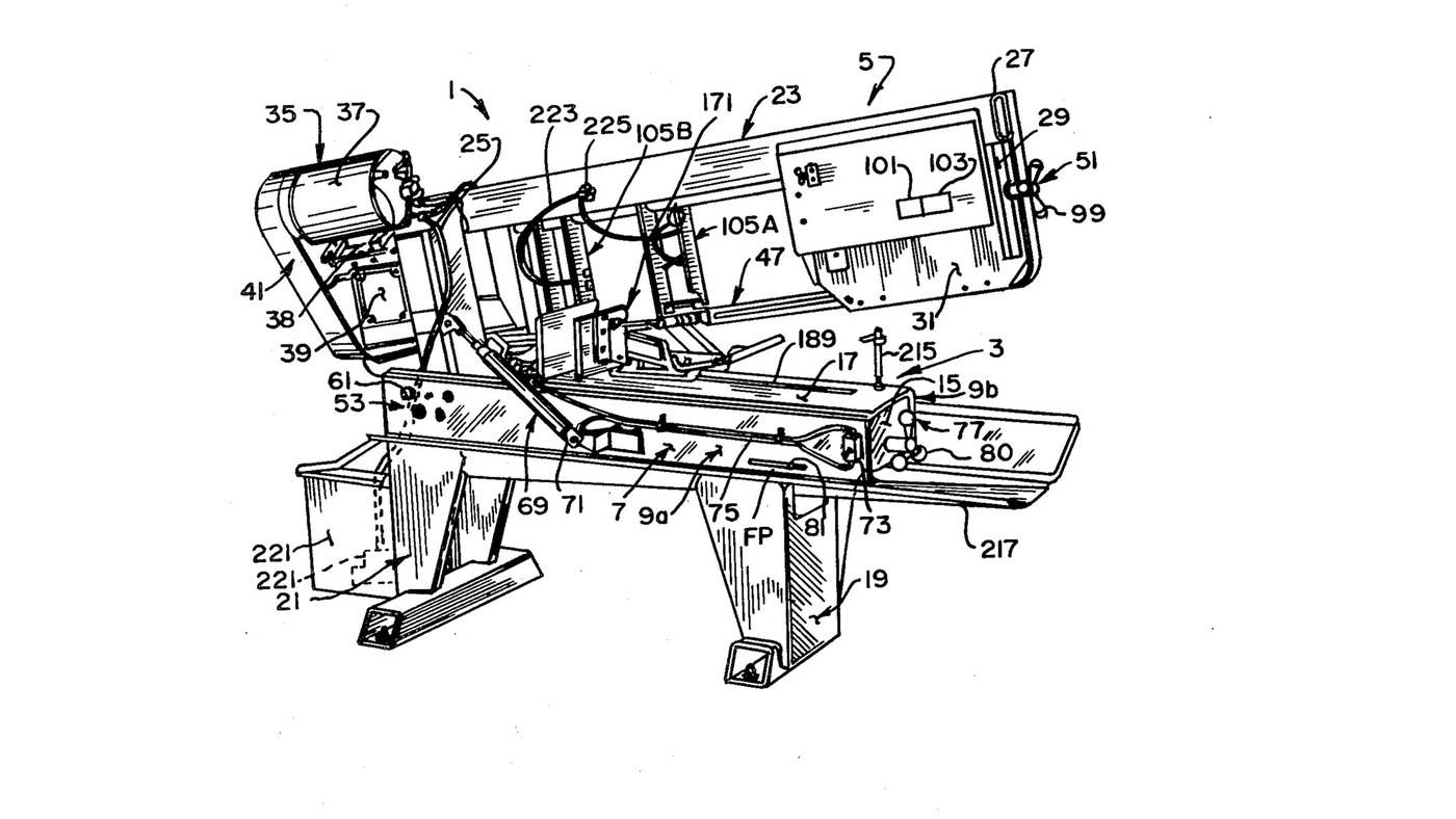
Curtis Eccardt's horizontal power band saw (Emerson Electric, US 4,364,294, 1982), built from welded steel channel and tube instead of iron castings to cut its cost. The saw head swings down on trunnions over the bed; a hydraulic cylinder with a valve sets how fast it feeds, a spring counterbalances it, and a spring tensioner shows the blade tension on a scale. Two guides with rollers twist the blade's lower run 90° so its teeth face down into the work, and carbide inserts hold it there. The patent gives no sizes, speeds or ratings; the welder and wrenches are ours. The picture: the patent's Fig. 1.
Avancé
4 days

Consignes

1

Weld the bed

Stand two steel channels (9a, 9b) parallel, webs upright and flanges facing in, and weld gussets (15) between their webs. Bolt a bed plate (17) across the top flanges as the work surface. Ours: MIG welder, drill press for the bolt holes.

Matériaux pour cette étape :

Profilé en U en acierProfilé en U en acier2 pièces
Plaque d'acier douxPlaque d'acier doux1 pièce
Boulon à tête hexagonale - classe 8.8Boulon à tête hexagonale - classe 8.81 pièce

Outils nécessaires :
Poste à souder MIGPoste à souder MIG
Perceuse à colonnePerceuse à colonne
Clé à moletteClé à molette
2

Weld and bolt on the legs

Weld formed sheet-steel legs onto horizontal floor members to make front and rear leg weldments (19, 21), and bolt them under the bed.

Matériaux pour cette étape :

Tôle d'acierTôle d'acier1 pièce
Tube d'acierTube d'acier1 pièce
Boulon à tête hexagonale - classe 8.8Boulon à tête hexagonale - classe 8.81 pièce

Outils nécessaires :

Poste à souder MIGPoste à souder MIG
Clé à moletteClé à molette
3

Weld the head

Weld a head post (25) of square or rectangular steel tube square to a head beam (27) of rectangular tube. Weld a bracket leg (29) down from the beam's outer end, and fix support plates at both ends (31, 33).

Matériaux pour cette étape :

Tube d'acierTube d'acier1 pièce
Plaque d'acier douxPlaque d'acier doux1 pièce

Outils nécessaires :

Poste à souder MIGPoste à souder MIG
4

Fit the trunnions and align the pivot

Fix a shaft through the head post with its ends out as trunnions (55a, 55b), in bushings in two bearing blocks (59a, 59b) bolted inside the channel webs. Each block has one close-fit bolt hole and three oversize ones: shift the blocks until the pivot is parallel to the bed plate, then torque the bolts. A set screw (67) takes out end play.

Matériaux pour cette étape :

Arbre en acierArbre en acier1 pièce
Douille métalliqueDouille métallique2 pièces
Palier supportPalier support2 pièces
Boulon à tête hexagonale - classe 8.8Boulon à tête hexagonale - classe 8.88 pièces
Vis sans tête à bout cuvetteVis sans tête à bout cuvette1 pièce

Outils nécessaires :

Perceuse à colonnePerceuse à colonne
Clé dynamométriqueClé dynamométrique
5

Mount motor, belt drive and gearbox

Mount the electric motor (37) on a plate (38) pivoted on the head beam, and couple it by a multi-speed belt and pulleys (41) to a gearbox (39). Fit the drive wheel (43) on the gearbox output shaft.

Matériaux pour cette étape :

Moteur électriqueMoteur électrique1 pièce
Plaque d'acier douxPlaque d'acier doux1 pièce
Courroie de transmissionCourroie de transmission1 pièce
PouliePoulie1 pièce
Réducteur à engrenagesRéducteur à engrenages1 pièce
Volant de scie à rubanVolant de scie à ruban1 pièce

Outils nécessaires :

Clé à moletteClé à molette
6

Build the idler tensioner

Weld an idler yoke (87) of rolled steel plate, pivot it on the head beam with a pin (89), and cantilever the idler axle from it with the idler wheel (45) on bearings (85). A threaded rod (91) pulls the yoke through a coil spring (93) held between compression plates and a U-bolt (97); a knob (99) turns the rod. An indicator (101) on the spring reads the tension on a scale (103).

Matériaux pour cette étape :

Plaque d'acier douxPlaque d'acier doux1 pièce
Goupille en acierGoupille en acier1 pièce
Arbre en acierArbre en acier1 pièce
Volant de scie à rubanVolant de scie à ruban1 pièce
Roulement à billesRoulement à billes1 pièce
Tige filetéeTige filetée1 pièce
Coil SpringCoil Spring1 pièce
Étrier en UÉtrier en U1 pièce
Bouton de commandeBouton de commande1 pièce

Outils nécessaires :

Poste à souder MIGPoste à souder MIG
Clé à moletteClé à molette
7

Build the two blade guides

In each guide channel (111) mount two guide rollers (115a, 115b) on ball bearings on eccentric bushings, one fixed and one adjusted to the blade thickness. Add a carbide thrust insert (133) on the blade's back edge and two carbide side inserts (137a fixed, 137b on a sprung swing bracket set by a bolt and knob). Clamp the guides on two bar tracks (107).

Matériaux pour cette étape :

Galet de guidageGalet de guidage4 pièces
Roulement à billesRoulement à billes4 pièces
Bague excentriqueBague excentrique4 pièces
Plaquette en carburePlaquette en carbure6 pièces
Coil SpringCoil Spring2 pièces
Bouton de commandeBouton de commande2 pièces
Tube d'acierTube d'acier1 pièce

Outils nécessaires :

Clé à moletteClé à molette
8

Fit the blade and set the tension

By hand, run the endless blade (47) round the drive and idler wheels and through both guides; the rollers twist its lower run about 90° so the teeth face down. Turn the tension knob until the scale shows the tension you want.

Matériaux pour cette étape :

Lame de scie à rubanLame de scie à ruban1 pièce
9

Fit the feed cylinder and counterbalance

Connect a hydraulic cylinder (71) between bed channel and head post above the trunnions, filled with oil and piped through tubing (75) to a control valve (73): the valve sets the feed rate and, closed, holds the head. Fit a coil spring (78) on a threaded linkage (79) between an end gusset and the head post below the trunnions, adjusted by a knob (80), to counterbalance the head.

Matériaux pour cette étape :

Vérin hydrauliqueVérin hydraulique1 pièce
Huile hydrauliqueHuile hydraulique1 batch
Tube hydrauliqueTube hydraulique1 pièce
Régulateur de débitRégulateur de débit1 pièce
Coil SpringCoil Spring1 pièce
Tige filetéeTige filetée1 pièce
Bouton de commandeBouton de commande1 pièce

Outils nécessaires :

Clé à moletteClé à molette
10

Bolt on the vice

Bolt the quick-acting vice to the bed plate to clamp the work square under the blade.

Matériaux pour cette étape :

Étau de machineÉtau de machine1 pièce
Boulon à tête hexagonale - classe 8.8Boulon à tête hexagonale - classe 8.81 pièce

Outils nécessaires :

Clé à moletteClé à molette

Matériaux

29

Outils requis

4

CC0 Domaine public

Ce blueprint est publié sous CC0. Vous êtes libre de copier, modifier, distribuer et utiliser ce travail pour tout usage, sans demander la permission.

Soutenez le Maker en achetant des produits via son Blueprint où il perçoit une Commission Maker définie par les Vendeurs, ou créez une nouvelle itération de ce Blueprint et incluez-le comme connexion dans votre propre Blueprint pour partager les revenus.

Commentaires

(0)

Se connecter pour participer à la discussion

Chargement des commentaires...