Collaboration
ART
BEAUTÉ ET BIEN-ÊTRE
ARTISANAT
CULTURE ET HISTOIRE
DIVERTISSEMENT
ENVIRONNEMENT
NOURRITURE ET BOISSONS
INGÉNIERIE INVERSE
SCIENCES
SPORTS
TECHNOLOGIE
TECHNOLOGIE PORTABLE
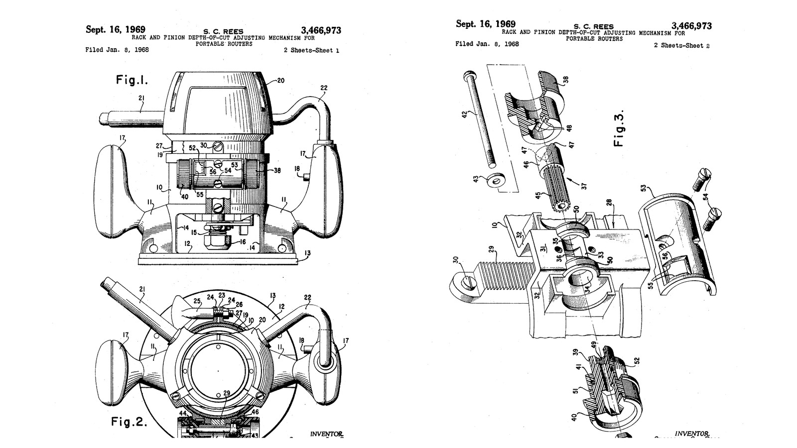

Rack-and-Pinion Router With a Zero-Set Knob: Two Knobs on One Hollow Pinion, Set to Zero on the Work (Rees, 1969)
Spencer C. Rees of Pickens, South Carolina, received US 3,466,973, dated 16 September 1969, for The Singer Company. A rack screwed to the motor housing is moved by a pinion through a window in a box on the base. The pinion is a hollow shaft running in one bore through the box's two side lugs, with a knob at each end. One knob turns it. The other, a zero-set knob with graduations, slips on its sleeve against an O-ring, so it can be set to zero with the bit touching the work. One screw through the middle holds it all together. Only the pinion shaft was metal; the rest was moulded.
We print every part in PETG round a small DC motor. The sizes are ours.
Avancé
About 3 days
Consignes
1
1
What one turn of the knob does
What one turn of the knob does
Chargement du notebook Jupyter…
2
2
Read US 3,466,973
Read US 3,466,973
"The zero-set knob 40 has a reduced diameter portion 51 which carries circumferentially-spaced graduation marks 52 on its surface." "In the above-described structure it will be noted that the only metallic part required is the pinion shaft 37 which is a relatively simple two-diameter piece."
3
3
Print the base
Print the base
The base 10: the split ring with clamp lugs, the box 28 for the rack with its two lugs 50 and stepped bore 33, the window 36, two legs 11 down to the plate 12 with its aperture, and two handle arms. Print it plate down. PETG, 0.2 mm layers, 40 % infill, 5 walls.
4
4
Print the motor housing
Print the motor housing
The housing 19: a tube for a 42 mm motor, 56 mm outside, a ledge with an 18 mm hole and two M4 holes, and two M3 holes for the rack. Print it ledge down. PETG, 0.2 mm layers, 40 % infill, 5 walls.
5
5
Print the small parts
Print the small parts
One plate: the rack 29 (module 1.5), the hollow pinion shaft 37 with its toothed (splined) part, bearing part and end ribs, the adjusting knob 38 with grooves, the flanged sleeve 39, the zero-set knob 40 with 20 graduations and an O-ring groove, and the cover plate 53 with its window 55 and mark 56. PETG, 0.2 mm layers, 40 % infill, 5 walls.
6
6
Motor in the housing
Motor in the housing
Fit the collet adapter on the motor's shaft, stand the motor in the housing on its ledge and screw it down with two M4 screws; wire it through a toggle switch to the DC supply. Screw the rack to the housing's front with two M3 screws.
Matériaux pour cette étape :
 Filament PETG1 pièce
 Moteur électrique1 pièce
 Adaptateur à pince pour arbre moteur1 pièce
 Vis à tête cylindrique à six pans creux2 pièces
 Vis à métaux2 pièces
 Interrupteur à levier1 pièce
 Fil de câblage1 pièce
 Gaine thermorétractable1 pièce
Outils nécessaires :
 Imprimante 3D à filament (FDM)
 Alimentation en courant continu
 Fer à souder électrique
 Jeu de clés Allen
 Jeu de tournevis
 Ébavureur
7
7
Base and handles
Base and handles
Turn two hardwood handles 17 and bolt one to each arm with an M8 bolt. Slide the housing into the base with the rack in the box's channel, and put an M5 screw with a wing nut through the clamp lugs.
Matériaux pour cette étape :
 Planche de bois dur1 pièce
 Assortiment de boulons à tête hexagonale2 pièces
 Écrou hexagonal3 piècesVis à tête cylindrique à six pans creux1 pièce
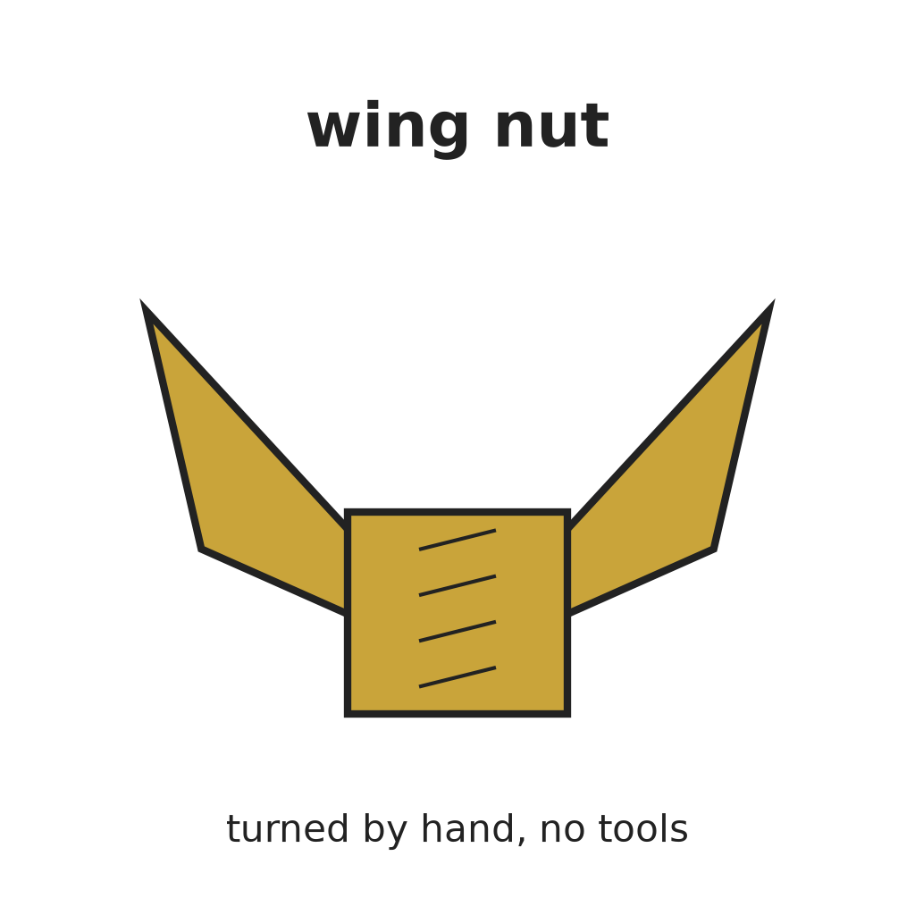 Écrou papillon1 pièce
Outils nécessaires :
 Tour à bois
 Perceuse sans fil
 Jeu de forets
 Clé à molette
8
8
Pinion, knobs and cover
Pinion, knobs and cover
Push the pinion shaft through the box's bore from the right, its toothed part through the window meshing with the rack, its bearing part in the right lug. Fit the O-ring in the zero-set knob's groove, push the sleeve into the knob, and slide them onto the shaft's toothed end from the left, the sleeve in the left lug. Fit the adjusting knob on the right end, its grooves on the shaft's ribs. Pass a long M4 screw through knob, shaft and sleeve with a washer, into a nut in the sleeve, and tighten it until the knobs have only a little end play. Screw the cover over the box with two M3 screws.
Matériaux pour cette étape :
 Joint torique1 pièceVis à tête cylindrique à six pans creux1 pièce
 Rondelle plate1 pièceÉcrou hexagonal1 pièceVis à métaux2 pièces
Outils nécessaires :
Jeu de clés AllenJeu de tournevis9
9
Set zero and rout
Set zero and rout
Fit a bit. Loosen the clamp, turn the adjusting knob until the bit's tip touches the work, then turn the zero-set knob alone until its zero lines up with the cover's mark. Turn the adjusting knob to the depth wanted, read off the graduations, and clamp. Rout with both hands on the handles.
Outils nécessaires :
 Coffret de fraises de défonceusePlanche de bois dur
 Serre-joint à pompe
 Pied à coulisse numérique 6 pouces
 Lunettes de sécurité
10
10
Troubleshooting
Troubleshooting
Rack and pinion router troubleshooting.
Flow
Loading...
11
11
History and honest limits
History and honest limits
**Spencer C. Rees** of Pickens, South Carolina, assignor to The Singer Company, US 3,466,973, dated 16 September 1969, filed 8 January 1968. He claimed a rack on the motor housing, "a pair of lugs formed on the base in fixed spaced relation on opposite sides of the rack and having aligned cylindrical apertures", a hollow pinion shaft, an adjusting knob, a flanged sleeve, "a zero-set knob frictionally coupled to said sleeve", and "single fastening means" through them all. His pinion shaft was metal and the rest moulded; ours is all printed. His motor ran on mains; ours is a small DC motor. He gives no sizes; every size here is ours.
Matériaux
14- 1 pièceEspace réservé
- 1 pièceEspace réservé
- Espace réservé
- Espace réservé
- 4 piècesEspace réservé
- Espace réservé
- Espace réservé
- 1 pièceEspace réservé
- 1 pièceEspace réservé
- Espace réservé
- 4 piècesEspace réservé
- 1 pièceEspace réservé
- 1 pièceEspace réservé
- 1 pièceEspace réservé
Outils requis
15- Espace réservé
- Espace réservé
- Espace réservé
- Espace réservé
- Espace réservé
- Espace réservé
- Espace réservé
- 1 vendor sell this, none ship to you yetEspace réservé
- Espace réservé
- Espace réservé
- 1 vendor sell this, none ship to you yetEspace réservé
- Espace réservé
- Espace réservé
- Espace réservé
- Espace réservé
Fichiers de conception
3Ce plan fabrique

Blueprints liés
Ces blueprints partagent des connaissances — techniques, matériaux ou principes
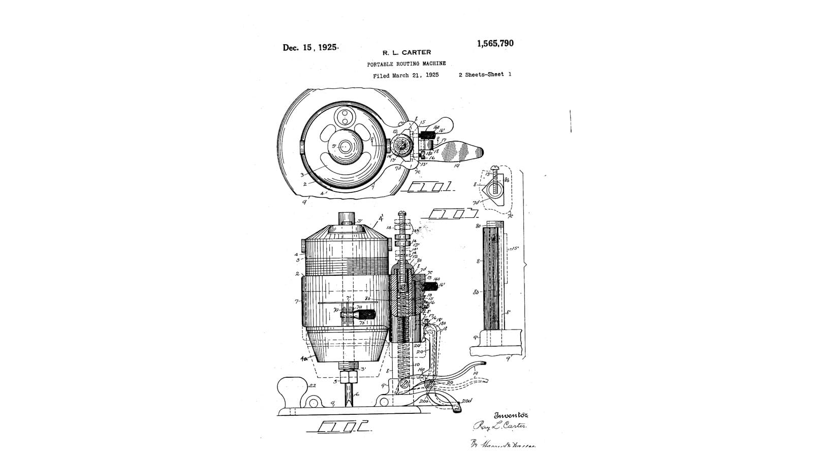
Rack-and-Pawl Plunge Router: The Motor Rides One Post on a Spring and Steps Down a Tooth at a Time (Carter, 1925)
par Forge
Menuiserie
15
0
0
0
0
0
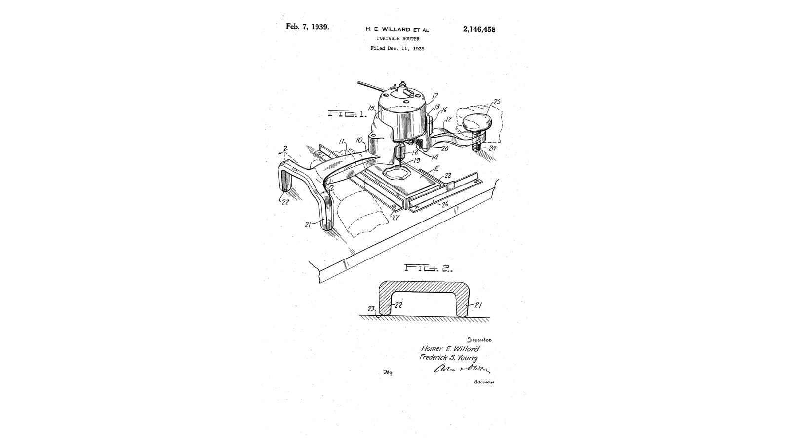
Three-Legged Router: A T-Frame on the Table Beside the Work, Its Depth Set by a Knob While Cutting (Willard & Young, 1939)
par Forge
Industry 3.0 — Assembly Line & Mass Production (1913)
7
0
0
0
0
0
CC0 Domaine public
Ce blueprint est publié sous CC0. Vous êtes libre de copier, modifier, distribuer et utiliser ce travail pour tout usage, sans demander la permission.
Soutenez le Maker en achetant des produits via son Blueprint où il perçoit une Commission Maker définie par les Vendeurs, ou créez une nouvelle itération de ce Blueprint et incluez-le comme connexion dans votre propre Blueprint pour partager les revenus.