

Loudspeaker
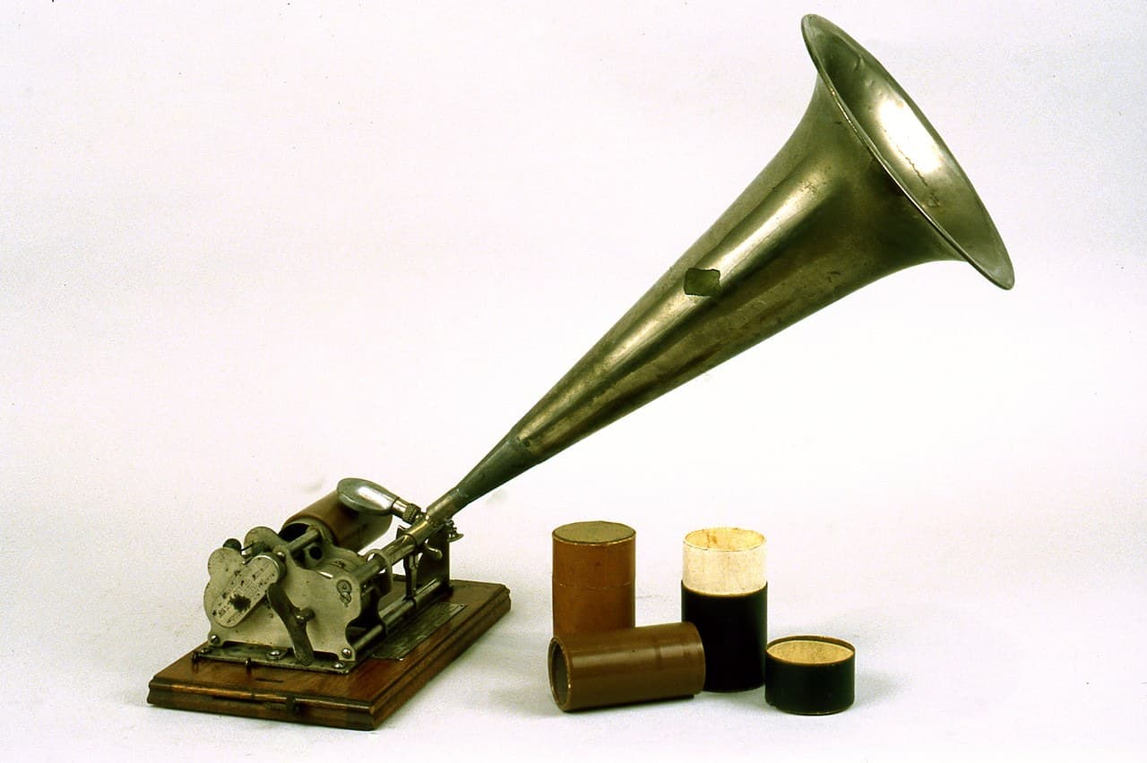
Early loudspeakers were telephone earpieces made bigger, or a horn bolted to a gramophone. Both are resonant: they reproduce the frequencies their own mechanics like and swallow the rest. Speech survives that treatment because speech is narrow. Music does not — the bass disappears, the top end turns shrill, and every recording sounds like it is coming through a tube, because it is.
The moving-coil answer is to stop the mechanism having a favourite note. Hang a light coil in a strong magnetic field, glue it to a stiff cone, and let the current in the coil push the cone directly. Nothing resonates by design — the cone goes where the signal says, across the whole audible range.
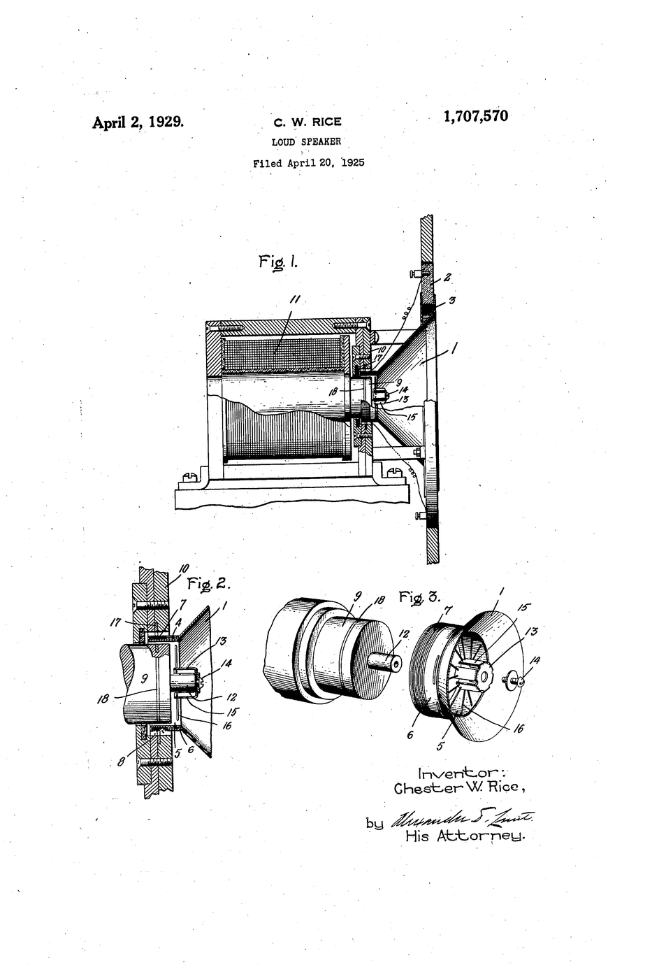
US Patent 1,707,570, "Loud-speaker", filed 20 April 1925 and granted 2 April 1929 to Chester W. Rice, assigned to General Electric. Its specific claim is subtler than the cone: copper rings set into the pole pieces, lowering the coil's impedance so the drive stays even as frequency rises.
Consignes
Keep magnets away from cards and pacemakers
Keep magnets away from cards and pacemakers
Strong neodymium magnets pinch hard enough to break skin and wipe bank cards. Handle one at a time and keep them clear of anyone with an implanted device.
Read US 1,707,570 and find the copper rings
Read US 1,707,570 and find the copper rings
Rice claims lowering the actuating coil's impedance with low-resistance copper rings acting as a short-circuited secondary in the pole pieces. Note that the cone is not what is claimed.
Listen to a horn first
Listen to a horn first
Roll a paper cone and hold it to a small sounder. Play music through it and note what is missing. This is the baseline the invention had to beat.
Wind the voice coil
Wind the voice coil
Wind about 40 turns of thin enamelled wire around a 25 mm cylindrical former. Keep the winding tight and even — a loose coil rubs in the gap and buzzes.
Matériaux pour cette étape :
 Fil de cuivre émaillé1 rouleau
Measure the coil resistance
Measure the coil resistance
Record the DC resistance. It should be a few ohms. Zero means a short between turns; open means a break at a solder joint.
Outils nécessaires :
 Multimètre numérique — sélection automatique, TRMS
Scrape and tin the enamel off the ends
Scrape and tin the enamel off the ends
The coating is an insulator. Unscraped ends read open circuit and the commonest build failure is right here.
Outils nécessaires :
 Pince plate
Cut and form the cone
Cut and form the cone
Cut a 150 mm paper disc, remove a wedge and join the edges into a shallow cone. Stiff and light — stiffness stops it flexing into its own resonances.
Glue the coil concentric to the cone apex
Glue the coil concentric to the cone apex
Fix the former to the cone's centre, square and centred. Any tilt will drag on the magnet later.
Suspend the cone so it moves only axially
Suspend the cone so it moves only axially
Fit a corrugated paper ring from the cone rim to a frame. It must be free along the axis and stiff sideways — that constraint keeps the coil out of the pole faces.
Matériaux pour cette étape :
 Contreplaqué de bouleau de Baltique1 feuille
Set the magnet in the coil's gap
Set the magnet in the coil's gap
Position a disc magnet so the coil hangs around it without touching anywhere through its travel. Spin the cone gently and listen for rubbing.
Feed a low-frequency tone and watch it move
Feed a low-frequency tone and watch it move
Drive the coil with a 40 Hz signal at low level. The cone visibly pumps in and out. Current in a field becomes motion — nothing else is happening.
Outils nécessaires :
 Alimentation de laboratoire
Sweep the frequency and listen for holes
Sweep the frequency and listen for holes
Sweep 50 Hz to 10 kHz and note where the output sags or peaks. Compare the evenness against the horn in step 3.
Measure coil impedance against frequency
Measure coil impedance against frequency
Record the coil's impedance at several frequencies. It rises with frequency — the coil's own inductance fights the drive, and the treble weakens.
Add Rice's copper ring
Add Rice's copper ring
Fit a closed copper ring around the pole near the coil and re-measure step 13. The impedance rise flattens: the shorted ring opposes the changing flux. This is the actual patent.
History & Context — the patent says Rice, and only Rice
History & Context — the patent says Rice, and only Rice
The patent. US 1,707,570, "Loud-speaker", filed 20 April 1925 and granted 2 April 1929, assigned to General Electric.
🔴 It names Chester W. Rice alone. This device is universally called the Rice-Kellogg loudspeaker, and the collaboration between Chester W. Rice and Edward W. Kellogg at GE is real and well documented — they presented the work together in 1925, and it reached the public as RCA's Radiola Model 104. But Edward W. Kellogg is not an inventor on this document. He filed separately (Serial No. 702,455) and the two also had a joint application (Serial No. 1,438), both referenced from within this patent. So "the Rice-Kellogg patent, US 1,707,570" is wrong in a small and very common way: the partnership is genuine, the co-inventorship on this particular number is not. Cite the pair for the work and Rice for this patent.
Why the copper ring is the claim and the cone is not. Moving-coil transducers were not new in 1925 — the principle dates to Ernst Siemens in the 1870s, and Oliver Lodge patented a moving-coil arrangement in 1898. What was missing was a design that stayed flat across the whole audio band. A voice coil is an inductor, and an inductor's impedance climbs with frequency, so a constant voltage delivers less and less current as the music goes up — the treble fades for purely electrical reasons before the cone even gets a chance. Rice's shorted copper rings sit in the magnetic circuit and act as a single-turn secondary: as flux tries to change, current in the ring opposes the change, flattening the inductance the coil presents. Step 13 and step 14 are the before-and-after of exactly that. Modern drivers still do this, and still call the part a shorting ring or Faraday ring.
What it unlocked. A speaker that reproduces the full range without a horn is the precondition for radio and recorded music becoming domestic objects rather than novelties: a horn is large, directional and coloured, and a cone driver is none of those. Public address, cinema sound, and eventually every recording that expected to be heard as the musicians intended, all sit downstream. The design has proved extraordinarily durable — a coil, a gap, a cone and a compliant surround is still what is in almost every speaker made a century later, and the build above is that same object at bench scale.
Its honest weakness. Direct radiation is inefficient. A horn couples the diaphragm to the air far better and can be many times louder for the same power, which is why horns never disappeared from stadiums and cinemas. Rice's design trades efficiency for accuracy — and, once amplification was cheap, that was the right trade.
Matériaux
2- 1 rouleauEspace réservé
- 1 feuilleEspace réservé
Outils requis
3- Espace réservé
- Espace réservé
- Espace réservé
Blueprints liés
Ces blueprints partagent des connaissances — techniques, matériaux ou principes
CC0 Domaine public
Ce blueprint est publié sous CC0. Vous êtes libre de copier, modifier, distribuer et utiliser ce travail pour tout usage, sans demander la permission.
Soutenez le Maker en achetant des produits via son Blueprint où il perçoit une Commission Maker définie par les Vendeurs, ou créez une nouvelle itération de ce Blueprint et incluez-le comme connexion dans votre propre Blueprint pour partager les revenus.