
Driving an RGB LED — SIK Circuit 3
Consignes
Parts & Introduction
Parts & Introduction
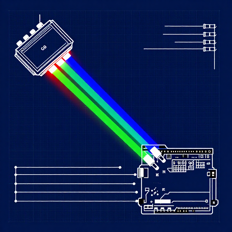
An RGB LED contains three tiny LEDs (red, green, blue) in one package. By mixing different brightness levels of each color, you can create any color in the rainbow. This experiment introduces analogWrite() for PWM output.
Parts Needed
- 1x Arduino Uno + USB cable
- 1x Breadboard
- 1x RGB LED (Common Cathode)
- 3x 330Ω Resistors
- 5x Jumper Wires
RGB LED Pin Order (flat edge facing you): Red, Ground (longest pin), Green, Blue.
Matériaux pour cette étape :
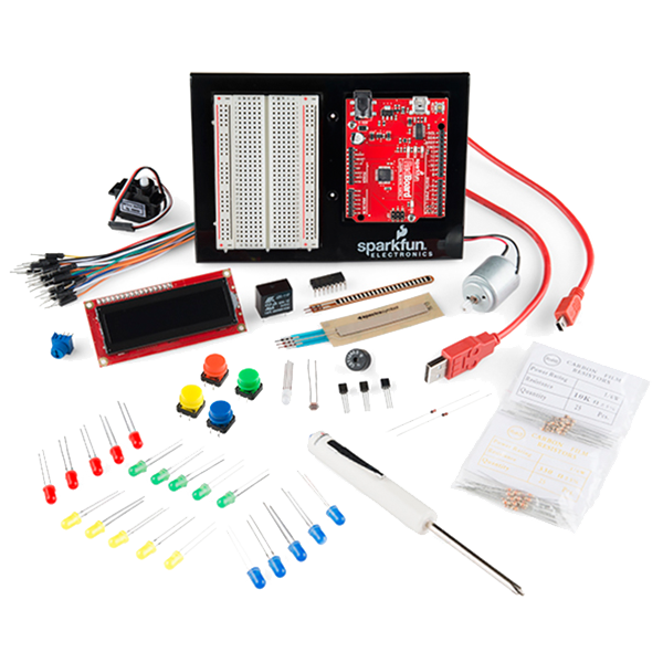 SparkFun Inventor's Kit - V3.21 kit
Outils nécessaires :
 Ordinateur avec l'IDE Arduino
Hardware Hookup
Hardware Hookup
Wiring Instructions
- Place the RGB LED in the breadboard. Identify pins from the flattened edge: Red, GND (longest), Green, Blue.
- Connect the GND pin (longest, second from left) to the GND rail.
- Connect the Red pin through a 330Ω resistor to Arduino Pin 9.
- Connect the Green pin through a 330Ω resistor to Arduino Pin 10.
- Connect the Blue pin through a 330Ω resistor to Arduino Pin 11.
Pins 9, 10, and 11 are all PWM-capable (marked with ~ on the board).
Matériaux pour cette étape :
 Ruban de LED RVB 5050 (non adressable)1 pièce
 Plaque d'essai1 pièce
 Fils de liaison5 pièces
Arduino Code
Arduino Code
Open the Arduino IDE and upload the following sketch to your Arduino board.
Matériaux pour cette étape :
 Arduino Uno R31 pièce
Outils nécessaires :
Ordinateur avec l'IDE ArduinoTest & Experiment
Test & Experiment
What You Should See
The LED cycles through 8 solid colors (off, red, green, blue, yellow, cyan, purple, white) for 1 second each, then smoothly fades through the entire color spectrum.
Troubleshooting
- Incorrect colors: With four pins close together, it's easy to misplace one. Double-check each connection.
- Red too bright: The red diode is often brighter. Try a higher-value resistor on the red pin, or reduce in code:
analogWrite(RED_PIN, redIntensity/3).
Experiments to Try
- Add a potentiometer to control which color is displayed.
- Create your own color sequences — try a "sunrise" effect (dark red → orange → yellow → white).
Matériaux
6- SparkFun Inventor's Kit - V3.210 % de commission1 kit€93.25
- Espace réservé
- Espace réservé
- Espace réservé
- Espace réservé
- 3 piècesEspace réservé
Outils requis
1- Espace réservé
CC0 Domaine public
Ce blueprint est publié sous CC0. Vous êtes libre de copier, modifier, distribuer et utiliser ce travail pour tout usage, sans demander la permission.
Soutenez le Maker en achetant des produits via son Blueprint où il perçoit une Commission Maker définie par les Vendeurs, ou créez une nouvelle itération de ce Blueprint et incluez-le comme connexion dans votre propre Blueprint pour partager les revenus.