Using a Flex Sensor — SIK Circuit 9
Consignes
Parts & Introduction
Parts & Introduction
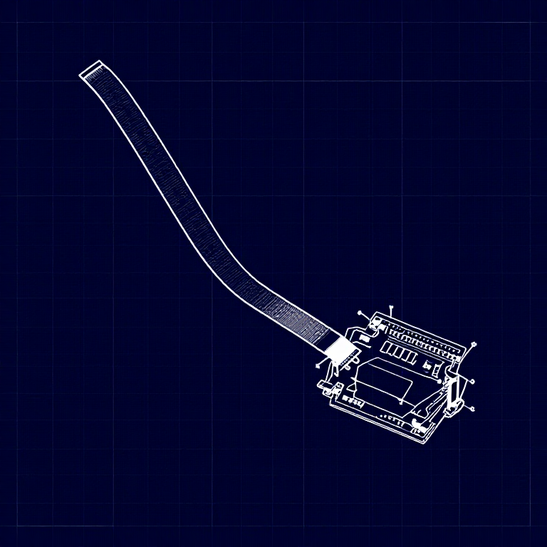
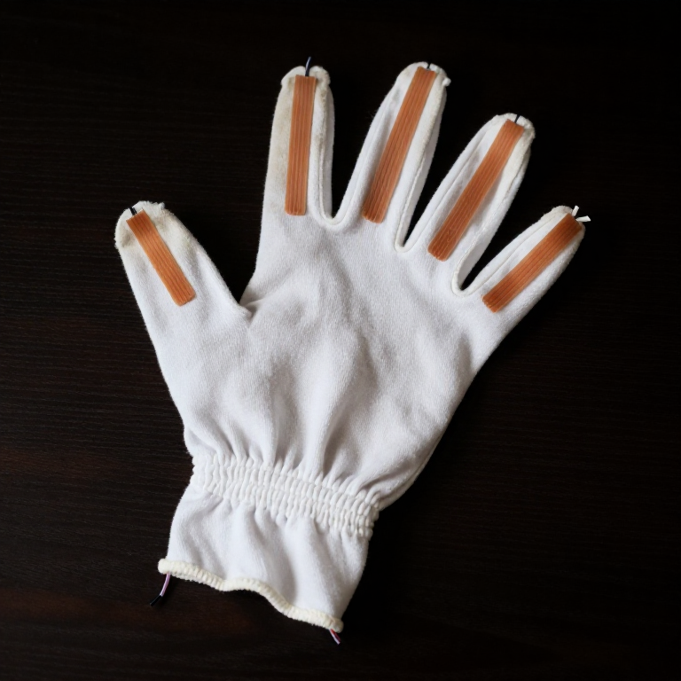
A flex sensor changes resistance when bent. Combined with the servo from Circuit 8, you can create gesture-based controls — bend the sensor to move the servo. This combines analogRead() with the Servo library.
Parts Needed
- 1x Arduino Uno + USB cable
- 1x Breadboard
- 1x Flex Sensor
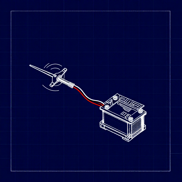
- 1x Servo Motor
- 1x 10KΩ Resistor
- 11x Jumper Wires
Matériaux pour cette étape :
 SparkFun Inventors Kit - V3.21 kit
 Flex Sensor1 pièce
 10K Ohm Resistor1 pièce
 Jumper Wires7 pièces
Outils nécessaires :
Hardware Hookup
Hardware Hookup
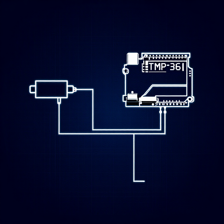
Wiring Instructions
Flex Sensor
- Connect one pin of the flex sensor to 5V.
- Connect the other pin to Analog Pin A0.
- Connect a 10K resistor from Analog Pin A0 to GND (voltage divider).
Servo
- Connect Red wire to 5V.
- Connect Black wire to GND.
- Connect White wire to Digital Pin 9.
Matériaux pour cette étape :
Flex Sensor1 pièce10K Ohm Resistor1 pièceJumper Wires7 piècesArduino Code
Arduino Code
Open the Arduino IDE and upload the following sketch to your Arduino board.
Matériaux pour cette étape :
Outils nécessaires :
Test & Experiment
Test & Experiment
What You Should See
The servo moves in response to bending the flex sensor. Open the Serial Monitor to see both the raw sensor value and the mapped servo position.
Troubleshooting
- Servo not moving: Check servo wiring — easy to plug in backwards.
- Sensor only works one way: The flex sensor bends in one direction. The striped side should face outward on a convex curve.
- Limited range: Adjust the
map()range values (600, 900) to match your sensor's actual readings from the Serial Monitor.
Experiments to Try
- Build a "robot finger" that mimics your finger bending.
- Replace the servo with an LED and control brightness by bending.
Matériaux
7- €90.00
- 1 pièceEspace réservé
- €3.00
- €4.00
Related blueprints
Other builds that share materials, tools, or techniques with this one.


CC0 Domaine public
Ce blueprint est publié sous CC0. Vous êtes libre de copier, modifier, distribuer et utiliser ce travail pour tout usage, sans demander la permission.
Soutenez le Maker en achetant des produits via son Blueprint où il perçoit une Commission Maker définie par les Vendeurs, ou créez une nouvelle itération de ce Blueprint et incluez-le comme connexion dans votre propre Blueprint pour partager les revenus.